Damper device

a damper device and damper technology, applied in the direction of shock absorbers, mechanical devices, gearing, etc., can solve the problems of large difference, difficult suppression of vibration noise, resonance of rear-differential units at the rotation input portion of the rotation input portion, etc., to achieve the effect of reducing vibration nois

Inactive Publication Date: 2011-06-07
TOYOTA JIDOSHA KK
View PDF8 Cites 3 Cited by
  • Summary
  • Abstract
  • Description
  • Claims
  • Application Information

AI Technical Summary

Benefits of technology

[0013]The invention provides a compact damper device that provides desired vibration-damping effects for multiple resonances largely different in frequency, and the invention further provides a drive-force transfer unit that incorporates the damper device to reduce vibration noises.
[0015]According to the damper device described above, in the first torsional damper constituted of the mass portion with the first inclined face and the elastic portion attached on said mass portion, the elastic portion deforms in a sheared manner under vibrations in the torsional directions and the elastic portion deforms in a compressed manner under vibrations in the longitudinal prying directions, or the like. Therefore, the longitudinal prying resonance frequency, or the like, of the first torsional damper can be adjusted as needed, while maintaining its torsional resonance frequency at a desired value, by setting the inclination angle of the first inclined face of the mass portion and the number of such inclined faces appropriately. On the other hand, in the second torsional damper constituted of the mass portion with the second inclined faces and the elastic portion attached on said mass portion, the elastic portion deforms in a sheared manner under vibrations in the direction of the rotational axis of the rotational element, vibrations in the longitudinal prying directions, and the like, and the elastic portion deforms in a compressed manner under vibrations in the torsional directions. Therefore, the torsional resonance frequency of the second torsional damper can be adjusted as needed, while maintaining its longitudinal prying resonance frequency, or the like, at a desired value, by setting the inclination angles of the respective second inclined faces of the mass portion and the number of the second inclined faces appropriately. Thus, using these torsional dampers, it is possible to provide a contact damper that provides desired vibration-damping effects for resonances largely different in frequency.
[0021]According to this structure, because the elastic portion of the first torsional damper is arranged between the first convex portion extending along the circumference of the first torsional damper and the first opposite concave portion that is opposed to the first convex portion, the rigidity of the elastic portion against vibrations in the axial direction, prying forces in the longitudinal direction, and the like, can be set to a proper value within a wide range by setting the number of the first convex portion and the first opposite concave portion, the inclination angle of the first inclined face, and so on, appropriately. As such, the longitudinal prying resonance frequency, or the like, of the first torsional damper can be properly adjusted to a target value, while maintaining its torsional resonance frequency at a desired value, even if said target value is largely different from the torsional resonance frequency of the first torsional damper. According to the above-described structure, further, because the elastic portion of the second torsional damper is arranged between the second convex portions spaced apart from each other along the circumference of the second torsional damper and extending in the axial direction of the rotational element and the second opposite concave portions that are opposed to the respective second convex portions, the rigidity of the elastic portion against vibration forces in the rotational directions can be set to a proper value within a wide range by setting the number of the second convex portions and the second opposite concave portions, the inclination angles of the respective second inclined faces, and so on, appropriately. As such, the torsional resonance frequency of the second torsional damper can be properly adjusted to a target value, while maintaining its longitudinal prying resonance frequency, or the like, at a desired value, even if said target value is largely different from the longitudinal prying resonance frequency, or the like, of the second torsional damper.
[0023]According to this structure, because the elastic portion of the first torsional damper is arranged between the first concave portion extending along the circumference of the first torsional damper and the first opposite convex portion that is opposed to the first concave portion, the rigidity of the elastic portion against prying forces in the longitudinal direction, and the like, can be set to a proper value within a wide range by setting the number of the first concave portion and the first opposite convex portion, the inclination angle of the first inclined face, and so on, appropriately. As such, the longitudinal prying resonance frequency, or the like, of the first torsional damper can be properly adjusted to a target value, while maintaining its torsional resonance frequency at a desired value, even if said target value is largely different from the torsional resonance frequency of the first torsional damper. According to the above-described structure, further, because the elastic portion of the second torsional damper is arranged between the second concave portions spaced apart from each other along the circumference of the second torsional damper and extending in the axial direction of the rotational element and the second opposite convex portions that are opposed to the respective second concave portions, the rigidity of the elastic portion against vibration forces in the rotational directions can be set to a proper value within a wide range by setting the number of the second concave portions and the second opposite convex portions, the inclination angles of the respective second inclined faces, and so on, appropriately. As such, the torsional resonance frequency of the second torsional damper can be properly adjusted to a target value, while maintaining its longitudinal prying resonance frequency, or the like, at a desired value, even if said target value is largely different from the longitudinal prying resonance frequency, or the like, of the second torsional damper.
[0027]The peak of the vibration that is caused on a case close to the end of the input shaft of the drive-side gear shaft due to the force applied from the mesh point between the drive-side gear shaft and the driven-side gear shaft is determined by the torsional resonance frequency of the drive-side gear shaft. According to the structure described above, therefore, the peak of said vibration can be suppressed by setting the torsional resonance frequency of the torsional damper having the first characteristic to a value close to the torsional resonance frequency of the drive-side gear shaft. On the other hand, the vibration peak of the drive-side gear shaft, which is determined by the vibration sensitivity of the case close to the input shaft of the drive-side gear shaft, can be suppressed by setting the resonance frequency of the torsional damper having the second characteristic to a value close to the bending resonance frequency of the input shaft of the drive-side gear shaft.
[0028]According to the invention, as described above, the longitudinal prying resonance frequency, or the like, of the first torsional damper that is constituted of the mass portion having the first inclined face extending along the circumference of the mass portion and the elastic portion attached on the mass portion can be adjusted as needed while maintaining its torsional resonance frequency at a desired value, and the torsional resonance frequency of the second torsional damper that is constituted of the mass portion having the second inclined faces extending in the axial direction of the rotational element and the elastic portion attached on the mass portion can be adjusted as needed while maintaining its longitudinal prying resonance frequency, or the like, at a desired value. Incorporating these torsional dampers, the damper device can be made a compact damper device that provides desired vibration-damping effects for multiple target resonances largely different in frequency.

Problems solved by technology

According to the technologies described in the above publications, however, it is still difficult to provide a compact damper device that provides desired vibration-damping effects for multiple target resonances having resonance frequencies largely different from each other.
For example, among various noises and vibrations that occur in a rear-drive vehicle, thrumming noises that are caused by resonances at the rotation input portion of a rear-differential unit and can be heard in the vehicle compartment are very difficult to suppress.
However, usually, there is a large difference (e.g., a difference of several hundreds hertz) between the resonance frequency of a damper device that is required to provide a sufficient vibration-damping effect for torsional resonances and the resonance frequency of the damper device that is required to provide a sufficient vibration-damping effect for longitudinal prying resonances.
According to related-art technologies, therefore, it is still difficult to provide a damper device that provides desired vibration-damping effects for two target resonances largely different in frequency but is compact enough to be fit in a limited space at the input portion of a differential unit.

Method used


Image

  • Damper device
  • Damper device
  • Damper device

Examples


first example embodiment

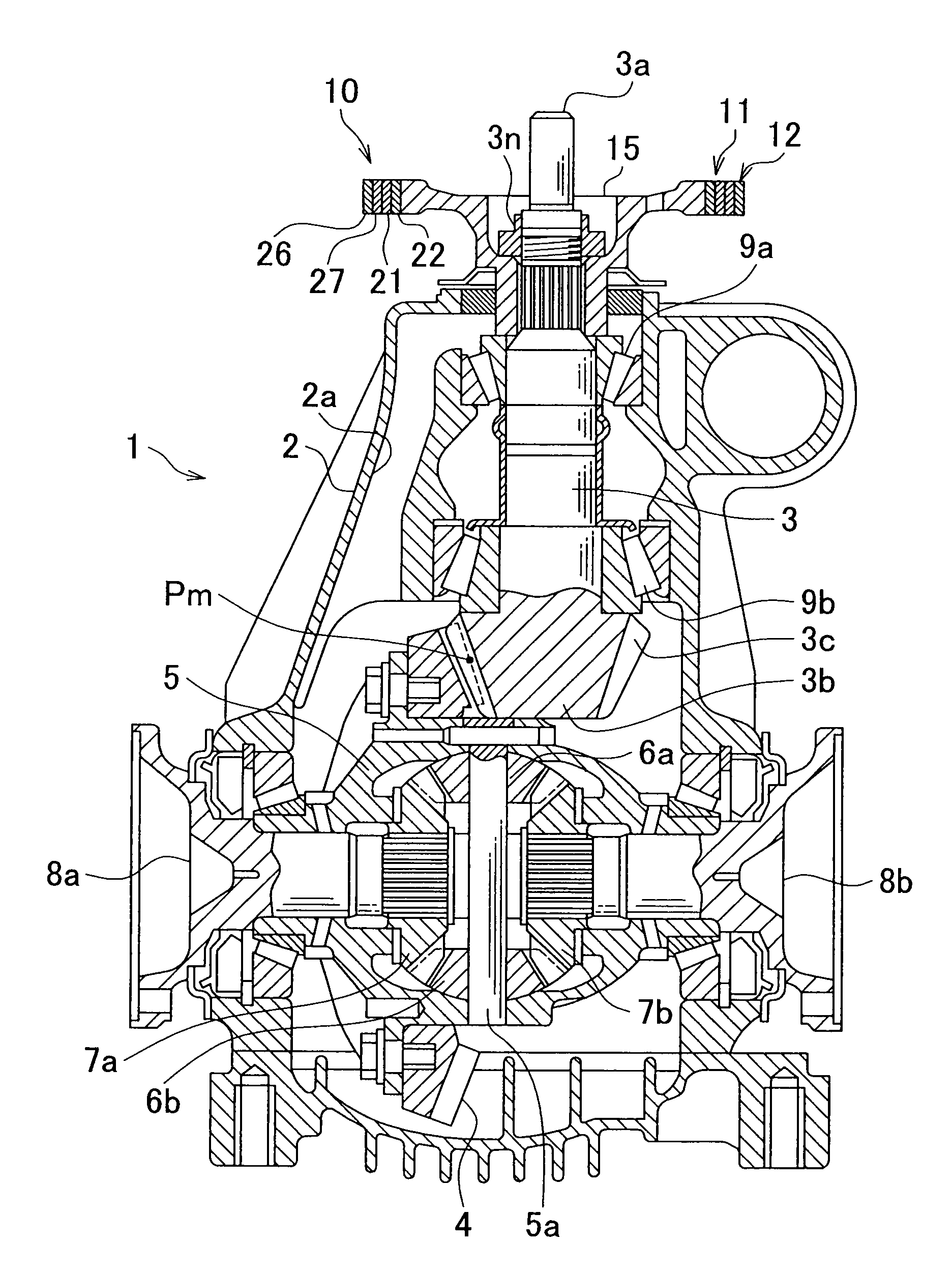
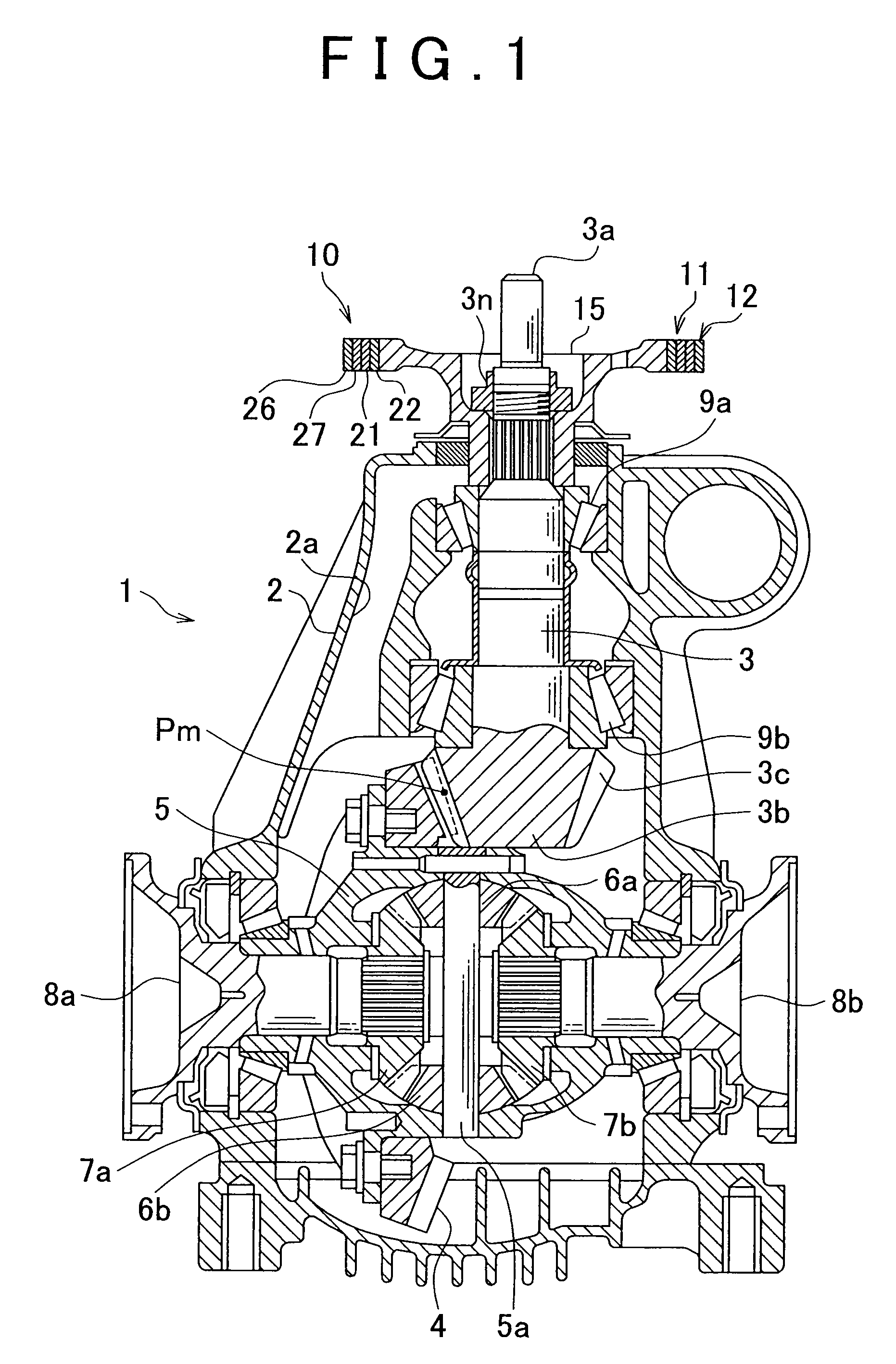
[0044]FIG. 1 is a cross-sectional side view of a drive-force transfer unit incorporating a damper device 10 according to the first example embodiment of the invention. FIG. 2 is a cross-sectional perspective view of a portion of the damper device 10. FIG. 3 is an enlarged cross-sectional side view of a portion of the damper device 10. FIG. 4 is an enlarged front view of a portion of the damper device 10. The damper device 10 is incorporated in a rear differential unit mounted in a rear-drive vehicle.

[0045]First, the structure of the damper device 10 will be described.

[0046]Referring to FIG. 1, the damper device 10 has torsional dampers 11, 12 having different characteristics. The torsional dampers 11, 12 are stacked on top of each other in a radial direction of the damper device 10. The torsional dampers 11, 12 are concentrically supported on a companion flange 15 that is a rotational element and rotates about the center axis of the damper device 10.

[0047]The companion flange 15 is ...

second example embodiment

[0074]FIG. 9 is an enlarged cross-sectional perspective view of a portion of a damper device 30 according to the second example embodiment of the invention, and FIG. 10 is an enlarged cross-sectional side view of a portion of the damper device 30, and FIG. 11 is a cross-sectional front view of a portion of the damper device 30. Like the above-described damper device 10 of the first example embodiment, the damper device 30 of the second example embodiment is provided at the input portion of a rear differential unit for rear-drive vehicles, and therefore the portions and parts of the damper device 30 of the second example embodiment that are identical to those of the damper device 10 of the first example embodiment are not identified in FIG. 9 to FIG. 11, and they are denoted, in the following description, by the same reference numerals as those used in the foregoing description on the first example embodiment.

[0075]Referring to FIG. 10, the damper device 30 has torsional dampers 31, ...

third example embodiment

[0088]FIG. 12 is an enlarged cross-sectional perspective view of a damper device 50 according to the third example embodiment of the invention.

[0089]Like the damper device 10 of the first example embodiment, the damper device 50 of the third example embodiment is provided at the input portion of a rear differential unit for rear-drive vehicles, and therefore the portions and parts of the damper device 50 that are identical to those of the damper device 10 of the first example embodiment are not identified in FIG. 12 and they are denoted, in the following description, by the same reference numerals as those used in the foregoing description on the first example embodiment.

[0090]Referring to FIG. 12, the damper device 50 of the third example embodiment has a torsional damper 51 having a first characteristic that enables the longitudinal prying resonance frequency, or the like, of the torsional damper 51 to be adjusted as needed while maintaining the torsional resonance frequency of th...


PUM

PropertyMeasurementUnit
resonance frequencyaaaaaaaaaa
massaaaaaaaaaa

Abstract

Mass portions of torsional dampers are annular surrounding corresponding elastic portions. The mass portion of the torsional damper has a first inclined face formed such that the elastic portion deforms in a sheared manner as the mass portion rotates in a rotational direction with respect to a companion flange and the elastic portion partially deforms in a compressed manner as the mass portion rotates in a direction other than the rotational direction. The mass portion of the torsional damper has second inclined faces formed such that the elastic portion deforms in a sheared manner as the mass portion rotates in the direction of the rotational axis of the companion flange and the elastic portion partially deforms in a compressed manner as the mass portion rotates in a direction other than the direction of the rotational axis.

Description

INCORPORATION BY REFERENCE[0001]The disclosure of Japanese Patent Application No. 2007-310936 on Nov. 30, 2007 including the specification, drawings and abstract is incorporated herein by reference in its entirety.BACKGROUND OF THE INVENTION[0002]1. Field of the Invention[0003]The invention relates to a damper device having a mass portion and an elastic portion, in particular, relates to a damper device incorporating a plurality of torsional dampers having different characteristics and together supported on a rotational element.[0004]2. Description of the Related Art[0005]One of damper devices that damp vibrations through dynamic vibration absorption at resonance frequencies is a torsional damper that damps torsional vibrations using mass portions and elastic portions, and this torsional damper is, for example, provided at the rotation input portion of a drive-force transfer unit, such as a differential unit for vehicles.[0006]As one of damper devices of the kind described above, Ja...

Claims


Application Information

Patent Timeline
Patent Type & Authority Patents(United States)
IPC IPC(8): F16H48/06F16F15/12
CPCF16F15/1435Y10T74/2131Y10T74/2121
Inventor MOCHIHARA, TAKAHIRO
Owner TOYOTA JIDOSHA KK
Why Eureka
Try Eureka