Method and device for producing a groove near an intended edge part of a conveyor belt, which groove is intended to be filled with a filler having sealing properties

a technology of conveyor belts and grooves, which is applied in the direction of textile selvedges, weaving, other domestic articles, etc., can solve the problems of large cutting force, large cost, and difficult to regrind layers of reinforced layers that adjoin the edge parts of conveyor belts, and achieves the effects of convenient and fast production, convenient operation and high production efficiency

Active Publication Date: 2011-06-07
FLEXIBLE STEEL LACING
View PDF10 Cites 0 Cited by
  • Summary
  • Abstract
  • Description
  • Claims
  • Application Information

AI Technical Summary

Benefits of technology

[0010]It is therefore an object of the present invention to eliminate the abovementioned disadvantages, at least partially, and / or to provide a usable alternative. In particular, it is an object of the invention to provide an inexpensive, quick, permanent and reliable method and device in order to produce a groove near an intended edge part of a conveyor belt, which groove is intended to be filled with a filter having sealing properties.
[0012]Advantageously, it is now possible to remove conveyor belt material from the surface of the conveyor belt, without a groove cutting element with a specially formed cutting edge being required for this purpose. Furthermore, it is advantageous that no means or parts of means have to be changed in order to carry out the method and produce a groove in a conveyor belt of arbitrary thickness.
[0014]Furthermore, the invention offers the possibility of removing conveyor belt material at a high or varying speed. Using the latter, it is also possible to produce a groove in a conveyor belt, in which the thickness of the remaining conveyor belt material measured at the position of the groove can be very thin. Thus, the method can be used for conveyor belts with a very thin coating layer, or in order to produce a deeper groove in a conveyor belt than is possible by means of the known method. This method may furthermore provide the possibility of using a first cutting element which is not very susceptible to wear. This offers the further advantage that, in order to form the groove, use may be made of a groove-cutting element in which the cutting forces are small, so that the risk of damage to the conveyor belt is small. In addition, the invention offers the advantage that, as a result of said higher or varying speed with which the conveyor belt material can be removed, it becomes attractive to carry out further operations on the conveyor belt at the same time as the step of removing material from said conveyor belt, since now only the additional operations can possibly determine the speed.
[0017]In a preferred embodiment according to the present invention, the relative position of the groove-cutting element relative to the bending element can be set. This offers the advantage that the production of the groove can be started and stopped at any position on the conveyor belt, as a result of which the system is suitable for, but not limited to, processing conveyor belts which have been made endless. In a production process for conveyor belts, it may be advantageous to make the conveyor belts endless before any further steps are carried out. In addition, if a drivably movable knife is used as the groove-cutting element, the cutting forces which are required in order to remove the conveyor belt material are advantageously low, as a result of which the removal speed can be high, while the groove can be produced accurately and the material thickness remaining at the groove can be very thin.

Problems solved by technology

A drawback of a conveyor belt constructed in this way is that the reinforcing layers with a porous, fibre-like structure adjoin the edge parts of the conveyor belt.
This makes it possible for impurities to penetrate the conveyor belt during use, which is not hygienic and therefore undesirable.
Knives provided with a trapezium or stepped cutting edge have the drawback that they have to be specially selected, tailored to the conveyor belt to be sealed, for example based on thickness and the position of the reinforcing layers.
They also have the disadvantage that they are relatively complicated, expensive and difficult to regrind.
In addition, the required cutting forces are considerable.
Due to the desired small remaining thickness at the groove, the conveyor belt is more susceptible to damage by the large cutting forces, as a result of which it is only possible in practice to produce a groove which is not as deep as is desired.
The large cutting forces furthermore require large driving forces to pull the conveyor belt through the machine.
It is very difficult to form a sufficiently straight groove in this way.
Because of the large amount of manual work involved, it is not possible to produce more than one groove at a time in a conveyor belt.

Method used


Image

  • Method and device for producing a groove near an intended edge part of a conveyor belt, which groove is intended to be filled with a filler having sealing properties
  • Method and device for producing a groove near an intended edge part of a conveyor belt, which groove is intended to be filled with a filler having sealing properties
  • Method and device for producing a groove near an intended edge part of a conveyor belt, which groove is intended to be filled with a filler having sealing properties

Examples


Embodiment Construction

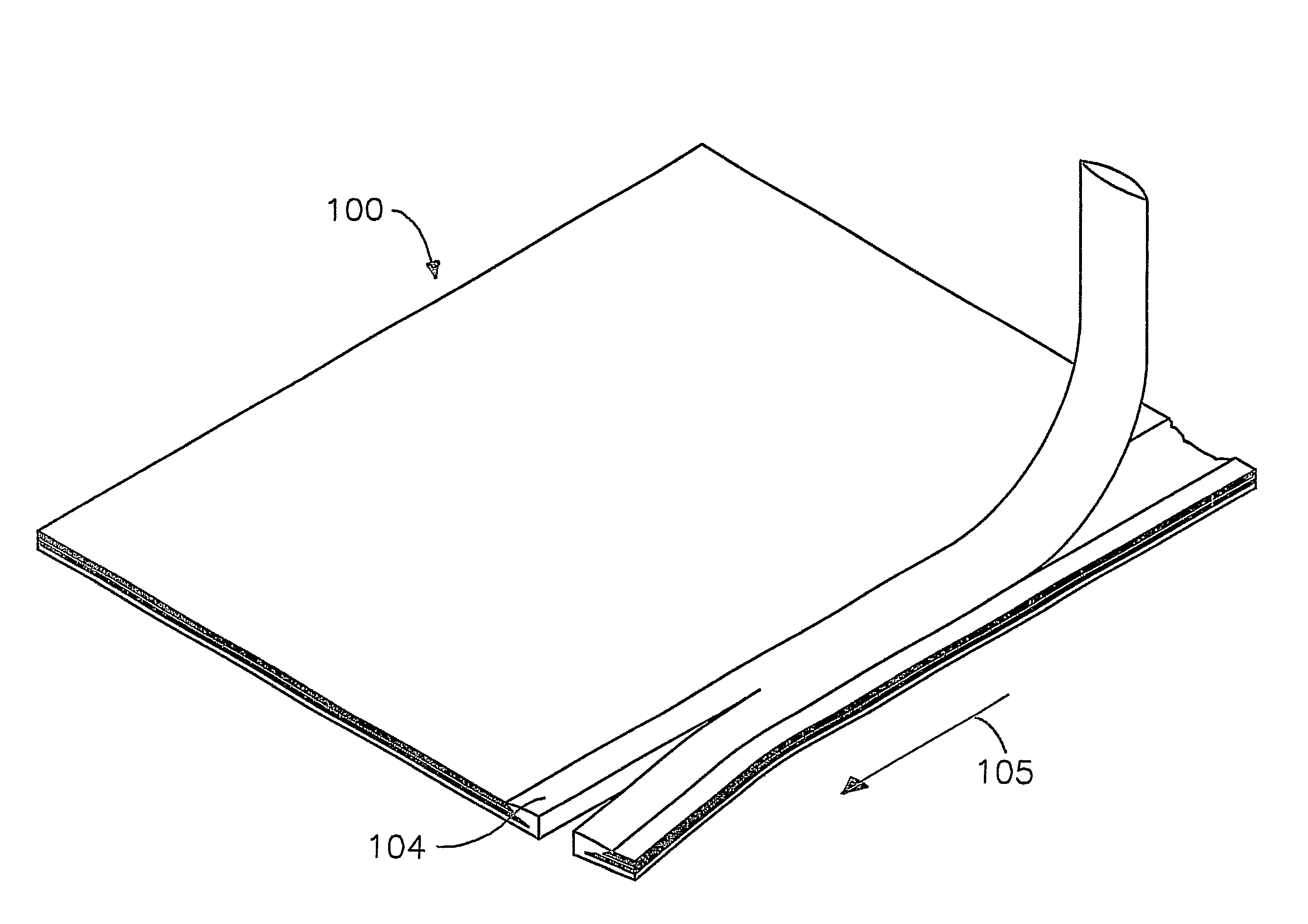
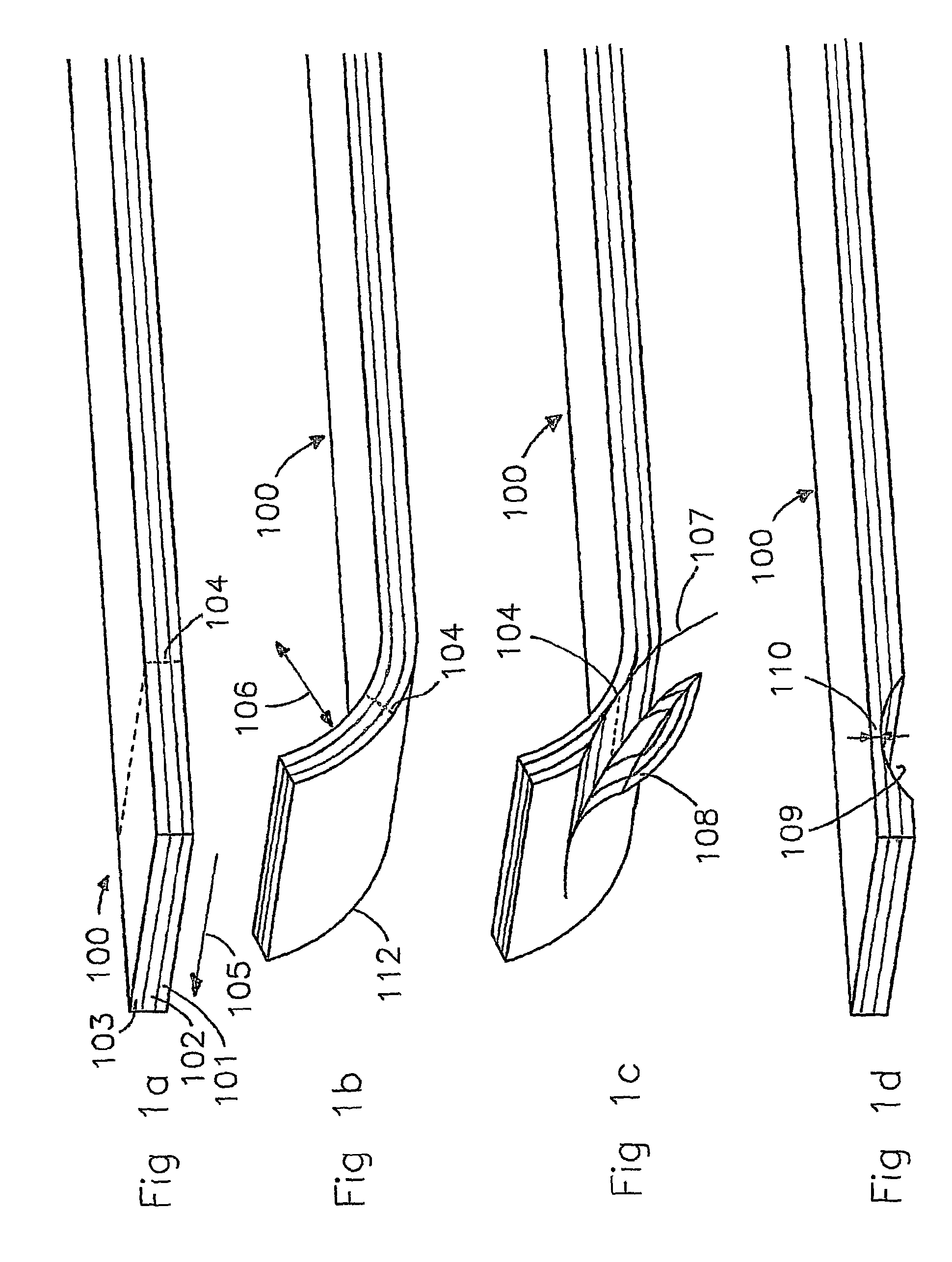
[0028]FIG. 1a only shows a strip of a conveyor belt 100, which is composed of a base layer 101, a reinforcing layer 102 and a coating layer 103 and having an intended edge part 104. The conveyor belt has a substantially flat shape, and extends lengthwise in the direction indicated by arrow 105. In particular, the strip forms part of a conveyor belt, more in particular of a conveyor belt which has been made endless.

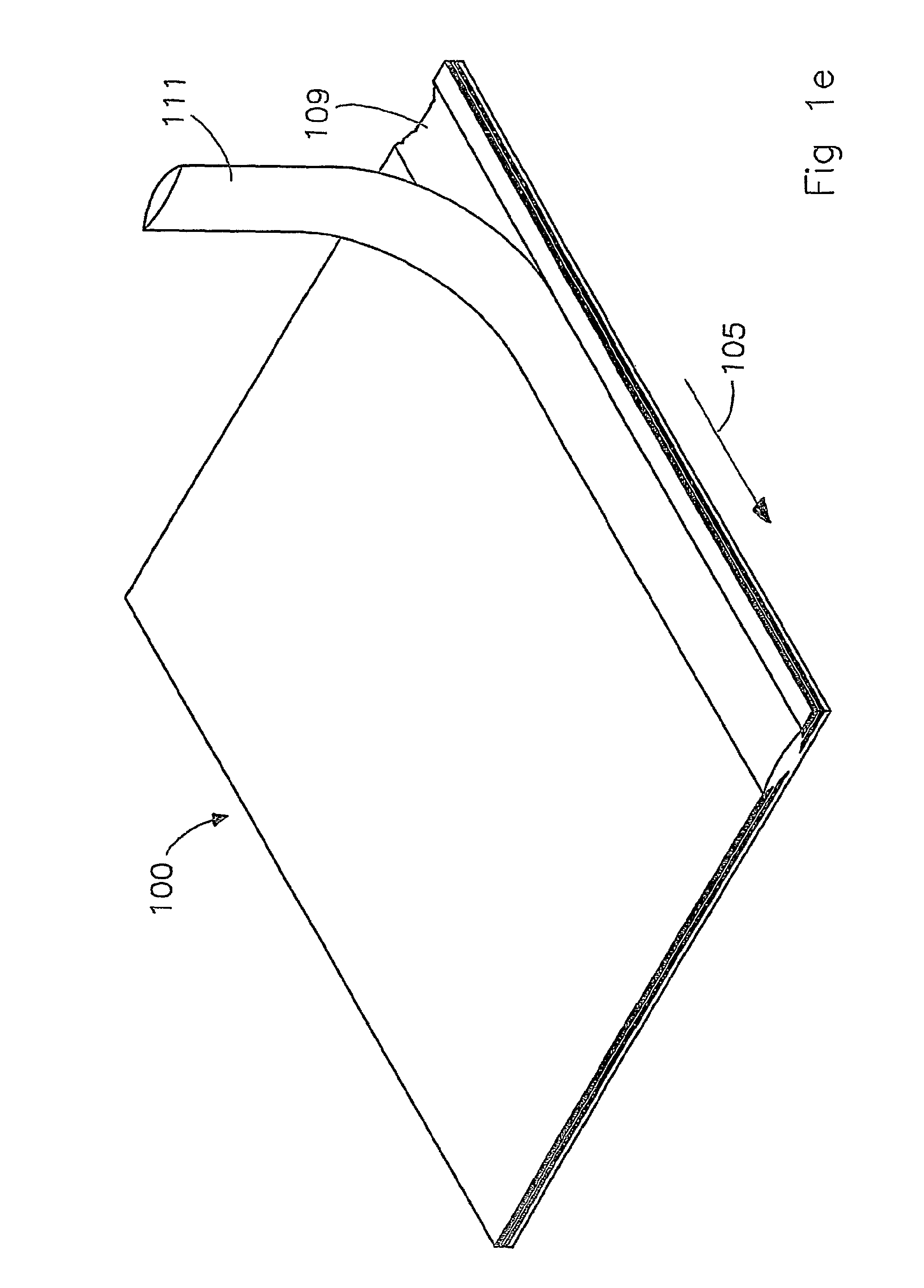
[0029]FIG. 1b shows the conveyor belt 100 from FIG. 1a, in which a curvature 112 with a radius 106 is provided at the position of the intended edge part 104. The curvature 112 is provided in a plane substantially at right angles to the longitudinal direction of the groove to be formed. The longitudinal direction of the groove to be formed in this case extends in the longitudinal direction 105 of the conveyor belt 100. The curvature 112 in this case as it were extends around the axial direction of the groove to be formed, i.e. around the longitudinal direction 105 indicated...


PUM

PropertyMeasurementUnit
radiusaaaaaaaaaa
radiusaaaaaaaaaa
radiusaaaaaaaaaa

Abstract

The present invention relates to a method and device for producing a groove near an intended edge part of a conveyor belt, which groove is intended to be filled with a filler having sealing properties, in which the groove is formed by removing conveyor belt material from one of the surfaces of the conveyor belt and in which, during the step of removing conveyor belt material, the conveyor belt is bent at the position of the groove to be formed near the intended edge part, and also to a conveyor belt in which a groove is produced in this manner.

Description

CROSS-REFERENCE TO RELATED APPLICATIONS[0001]This application is the National Stage of International Application No. PCT / NL2006 / 000557, filed Nov. 7, 2006, which claims the benefit of Netherlands Application No. NL 1030370, filed Nov. 8, 2005, the contents of which is incorporated by reference herein.FIELD OF THE INVENTION[0002]The present invention relates to producing a groove near an intended edge part of a conveyor belt, which groove is intended to be filled with a filler having sealing properties.BACKGROUND OF THE INVENTION[0003]Conveyor belts are a known means for conveying goods, for example raw materials, semi-finished products or products in a manufacturing environment for foodstuff, for example. In known embodiments, such conveyor belts are composed of one or more layers of material, each layer having different properties which are relevant for the quality and intended use of the conveyor belt. A customary construction for a conveyor belt is a coating layer, for example ma...

Claims


Application Information

Patent Timeline
Patent Type & Authority Patents(United States)
IPC IPC(8): B29D29/06
CPCB26D3/02B26D3/065B26D7/14B29D29/06B65G15/56B65G15/34Y10T156/1064Y10T156/108Y10T156/12Y10T156/1082Y10T83/0304Y10T83/9493Y10T83/343Y10T83/217Y10T83/323Y10T83/0424Y10T83/0405
Inventor VAN'T SCHIP, JOANNES STEFANUS
Owner FLEXIBLE STEEL LACING
Why Eureka
Try Eureka