Rotor position sensing system of brushless motor

a brushless motor and position sensing technology, applied in the direction of motor/generator/converter stopper, electronic commutator, dynamo-electric converter control, etc., can solve the problems of difficult control of phase delay to a fixed phase angle, inability to detect zero-cross points, and change of phase delay

Inactive Publication Date: 2011-06-07
DENSO CORP
View PDF13 Cites 13 Cited by
  • Summary
  • Abstract
  • Description
  • Claims
  • Application Information

AI Technical Summary

Benefits of technology

[0014]Therefore, an object of the invention is to provide an improved rotor position detecting circuit that can be applied to a brushless DC motor having delta-connected phase coils as well as a brushless DC motor having star-connected phase coils.
[0015]Another object of the invention is to provide an improved rotor position detecting circuit that can effectively reduce high-frequency noise generated during PWM switching control.
[0017]The first rotor position signal can indicate the rotor position over a rather wide speed range although the rotor position may be inaccurate. On the other hand, the second rotor position signal can indicate accurate rotor position at a limited speed range of the rotor. The above featured invention provides the accurate rotor position signal over a wide speed range by combining the first and second rotor position detecting circuits.
[0020]Therefore, the rotor position of the brushless DC motor can be accurately detected in much wider rotation speed range.

Problems solved by technology

Further, the phase delay changes when the temperature of the low-pass filter, which is usually disposed near the radiator of an automobile, changes.
Therefore, it is difficult to control the phase delay to a fixed phase angle, such as 90 degrees.
However, it is impossible to detect the zero-cross points when the rotation speed of the brushless DC motor becomes higher than a certain level due to current flowing through diodes each of which is connected across one of the MOSFETs of the inverter, as shown in FIG. 16A.
However, it is difficult to apply this system to a system that includes a brushless DC motor having delta-connected phase coils because it is necessary to connect a rotor position detecting circuit with the mechanical neutral point, which does not exist in the motor having the delta-connected phase coils.

Method used


Image

  • Rotor position sensing system of brushless motor
  • Rotor position sensing system of brushless motor
  • Rotor position sensing system of brushless motor

Examples


first embodiment

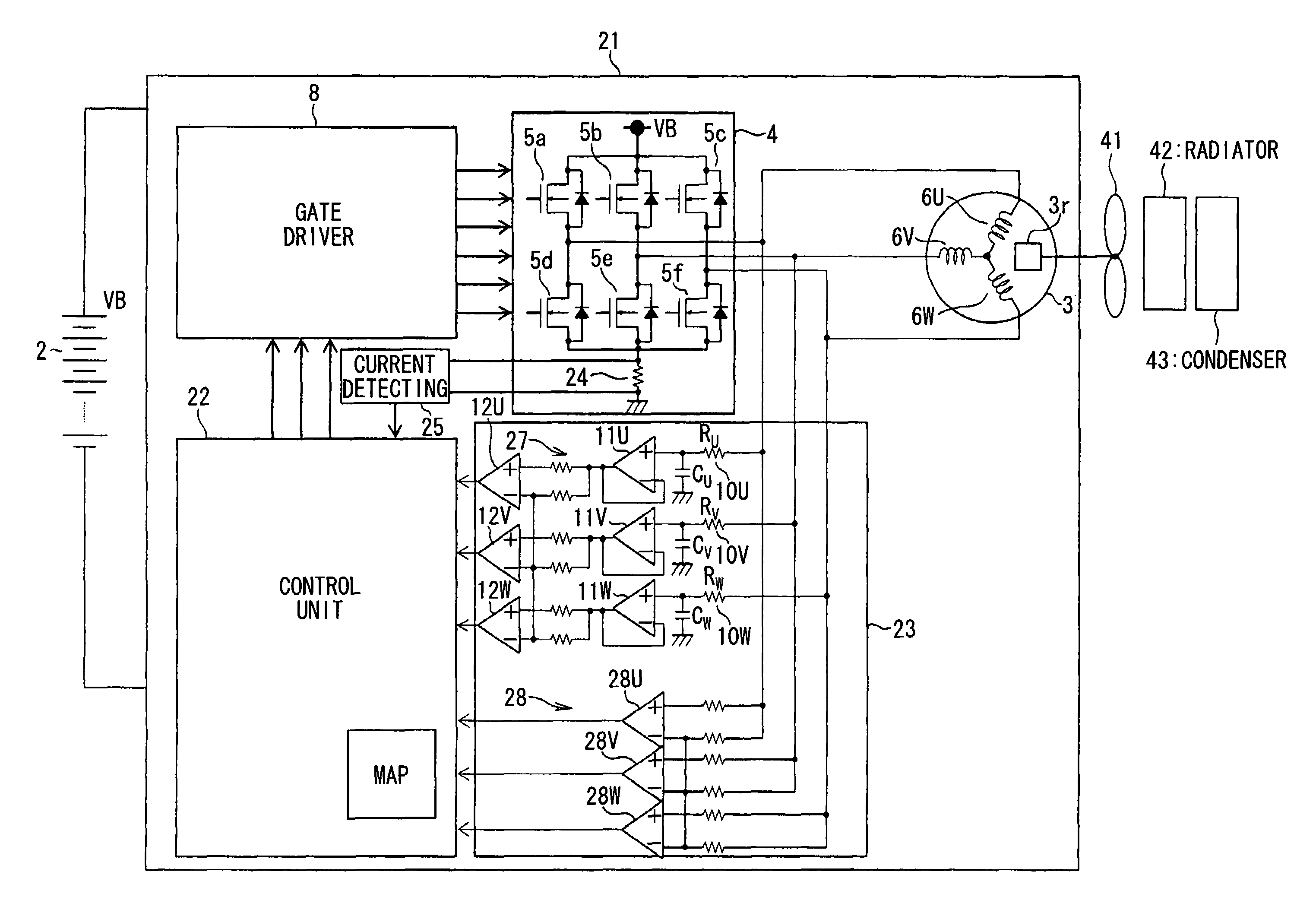
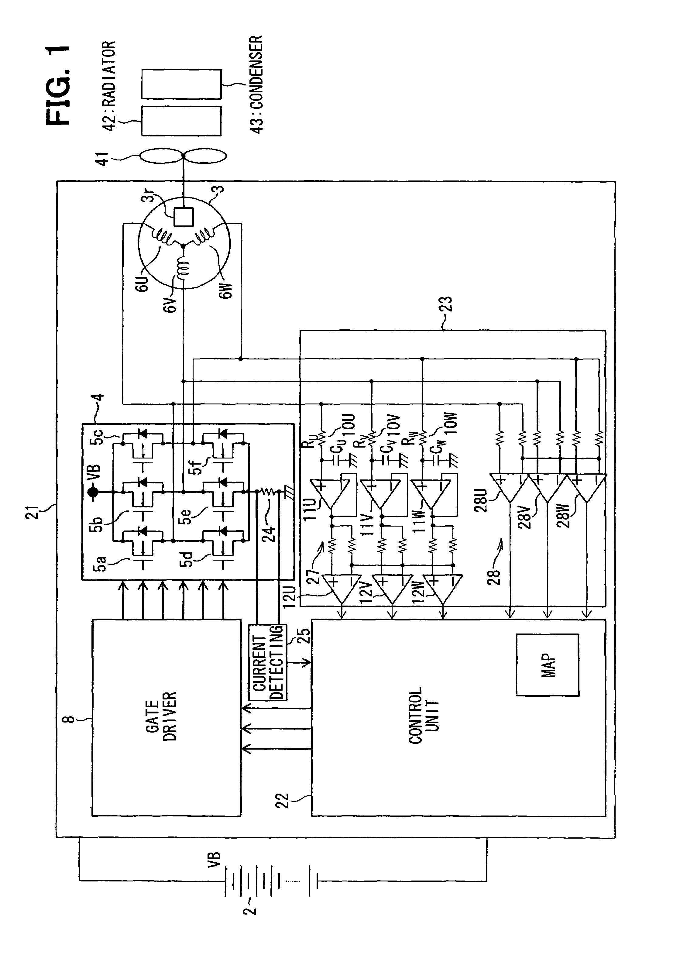
[0046]A brushless DC motor driving system 21 according to the invention will be described with reference to FIGS. 1-7. The brushless DC motor driving system 21 is powered by a battery 2 to drive a cooling fan 41 that supplies cooling air to a radiator 42 of a vehicle engine and a condenser 43 of an air condition system of a vehicle. The brushless DC motor driving system 21 includes a brushless DC motor 3, an inverter 4, a gate driver 8, a control circuit 22, a rotor position detecting circuit 23 and a current detecting circuit 25.

[0047]The brushless DC motor 3 has star-connected three phase coils 6U, 6V, 6W. The inverter 4 is constructed of a three-phase bridge circuit of six metal oxide semiconductor field-effect transistors (MOSFETs) 5a, 5b, 5c, 5d, 5e 5f that has three output terminals respectively connected with the three phase coils 6U, 6V, 6W of the DC motor 3 and a shunt resistor 24 that is connected between the sources of the low-side MOSFETs 5d, 5e, 5f and a ground. The shu...

second embodiment

[0082]A brushless DC motor driving system according to the invention will be described with reference to FIG. 5 and FIGS. 8A-8D.

[0083]In stead of step S7 shown in FIG. 5 where the maximum rotation speed is fixed to 2000 rpm, the maximum speed is changed according to the current detected by the current detecting circuit 25.

[0084]If the number of magnetic poles of the three-phase motor 3 is ten (10), the maximum rotation speed Nmax can be expressed as follows.

[0085]Nmax=(60 / t mask)×( 2 / 10)×(30 degrees / 360 degrees), where tmask is a masking time.

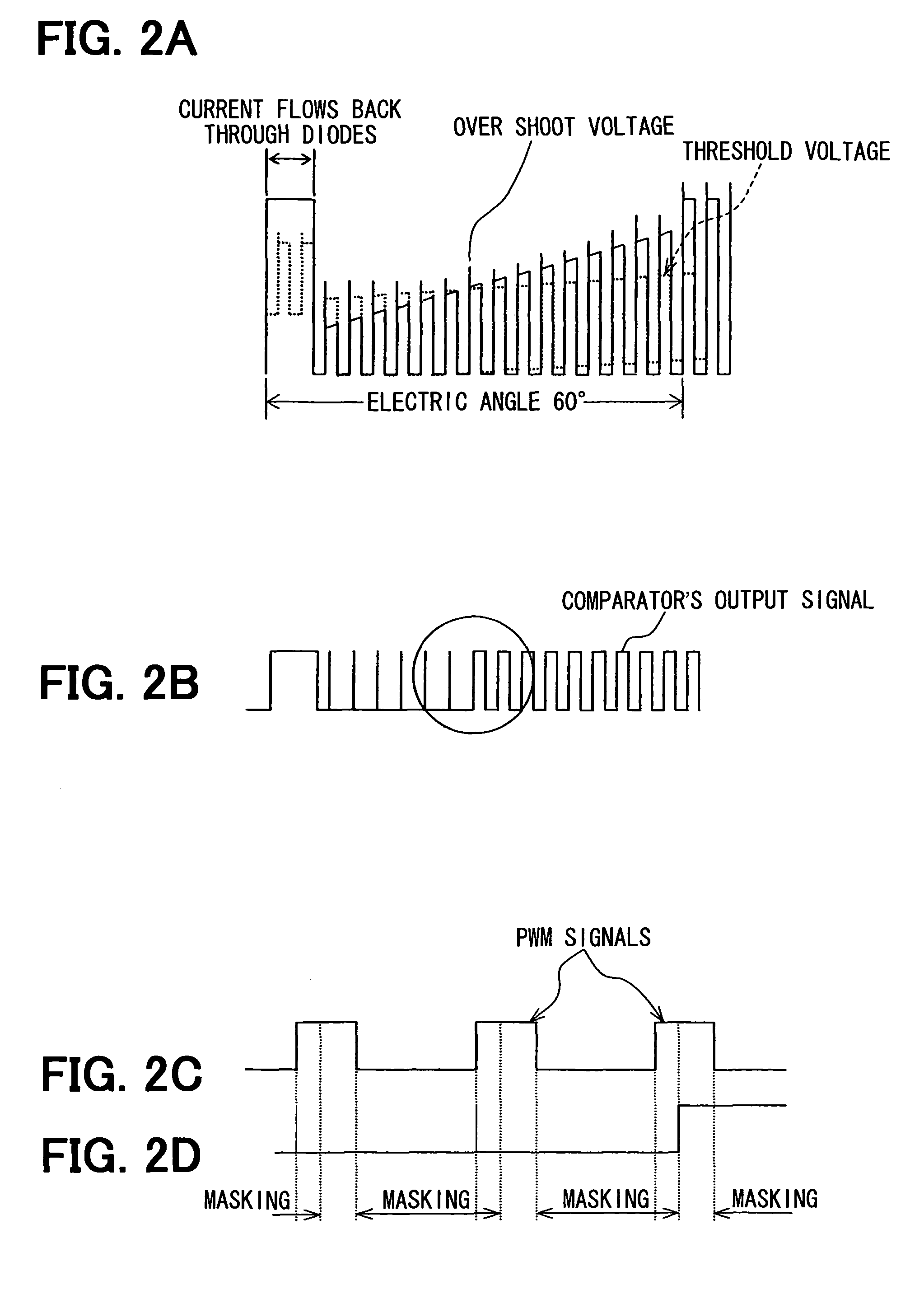
[0086]As shown in FIGS. 8A and 8B, the back-flow period and the maximum rotation speed Nmax increase linearly as the amount of the current increases. Accordingly, the control unit 22 sets the maximum rotation speed Nmax as shown in FIG. 8B, so that the operation speed range of the motor 3 can be made wider.

third embodiment

[0087]A brushless DC motor driving system according to the invention will be described with reference to FIG. 9.

[0088]This embodiment is almost the same as the first embodiment except for the operation of the control unit 22. That is, the step S7 of the first embodiment shown in FIG. 5 is replaced by steps S7L and S7H in this embodiment, as shown in FIG. 9. Whether the rotation speed is 500 rpm or more is examined at S7L, and whether the rotation speed is 2000 rpm or less is examined at S7H. If both of the examination results are YES, the steps S8-S12 of the first embodiment are subsequently carried out. If, on the other hand, any one of the examination results is NO, the steps S11, S12 of the first embodiment are subsequently carried out. After the step S10, the steps S13-S16 are parallelly carried out. Incidentally, the above steps may be carried out before the step S12. In more detail, whether the rotation speed is between 900 rpm and 1,000 rpm or not is examined at S13, and a ro...


PUM


Abstract

A rotor position detecting circuit includes a first position detecting circuit having a low-pass filter that shapes up phase voltage induced in a phase coil and a first comparator that compares the output voltage of the low-pass filter with a threshold level to form a first rotor position signal, and a second position detecting circuit having a second comparator that compares the phase voltage with a threshold voltage and a control unit that digitally processes the output voltage of the second comparator to form a second rotor position signal. The control unit corrects the first rotor position signal by the second rotor position signal to provide a final rotor position signal when the rotation speed of the brushless DC motor is in a measurable range.

Description

CROSS REFERENCE TO RELATED APPLICATION[0001]The present application is based on and claims priority from Japanese Patent Application 2007-140366, filed May 28, 2007 and Japanese Patent Application 2007-289855, filed Nov. 7, 2007, the contents of which are incorporated herein by reference.BACKGROUND OF THE INVENTION[0002]1. Field of the Invention[0003]The present invention relates to a brushless motor driving system for driving a brushless DC motor by sensing a rotor position of the rotor thereof, and in particular, a system and a method for sensing a rotor position of a brushless DC motor based on voltage induced in a phase coil of the brushless motor.[0004]2. Description of the Related Art[0005]JP-A-62-123979, JP-A-9-266690 and JP-A-7-288992 respectively disclose brushless DC motor driving system, in which brushless DC motors are operated based on the rotor position of their rotor that is detected by phase voltage induced in stator coils thereof.[0006]The brushless DC motor disclos...

Claims


Application Information

Patent Timeline
Patent Type & Authority Patents(United States)
IPC IPC(8): H02P6/06
CPCH02P6/18
Inventor KANAMORI, ATSUSHIYOSHIMURA, SATOSHI
Owner DENSO CORP
Why Eureka
Try Eureka