CNC instructions for solidification fixturing of parts

a technology of parts and instructions, applied in the field of total profile machining of parts, can solve the problems of high cost of rapid prototyping techniques, inability to achieve the physical attributes desired inability to achieve the physical attributes of the final part,

Active Publication Date: 2011-06-07
PROTOLABS INC
View PDF14 Cites 34 Cited by
  • Summary
  • Abstract
  • Description
  • Claims
  • Application Information

AI Technical Summary

Problems solved by technology

Many rapid prototyping techniques are expensive, and produce a part which, though to some degree dimensionally accurate even for many complex geometries, does not have the physical attributes desired of the final part.
Due to the expense on a per part basis, most rapid prototyping techniques are only used for low-volume runs of a part (such as a quantity of 10 or fewer), and not for mid- or high-volume part runs.
The process for generating CNC tool paths can be simple or difficult depending upon the complexity of the tool paths.
As part shape profiles and geometries are designed to be more complicated, CNC machining often requires the creation of custom fixtures for holding the part during machining.
It is not unusual for the design and fabrication of the custom fixturing to involve more time and expense than the design and fabrication of a single part itself.
With the added time and complexity associated with custom fixturing, CNC machining is rarely used for low-volumes of parts having more complex shapes which need to be fabricated in a quick turn-around time.
Particularly for mid- or high-volume runs, the tooling time required to CNC machine the part can be expensive.
These approaches can obstruct tool access to a significant amount of the part or require difficult repositioning of the part for multiple machining operations.
Relatively few fixturing methods are available which enable “total profile” machining, i.e., machining a substantial majority of the surface area of the part in the CNC machine.
While injection molded parts from Protomold can be achieved at a much lower cost than previously, the cost of one or two parts still requires creation of the injection mold and its associated cost.
Even the fast speed, low cost processing provided by First Cut Prototype may not be sufficient for some customers.
Extremely fast turn around times may be required for certain parts, which simply cannot await for the shipping time to get the parts from First Cut's machining locations to the customer's address.

Method used


Image

  • CNC instructions for solidification fixturing of parts
  • CNC instructions for solidification fixturing of parts
  • CNC instructions for solidification fixturing of parts

Examples


Embodiment Construction

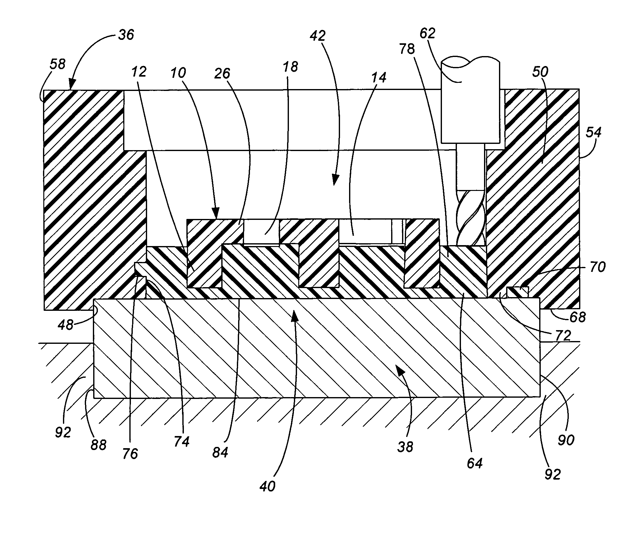
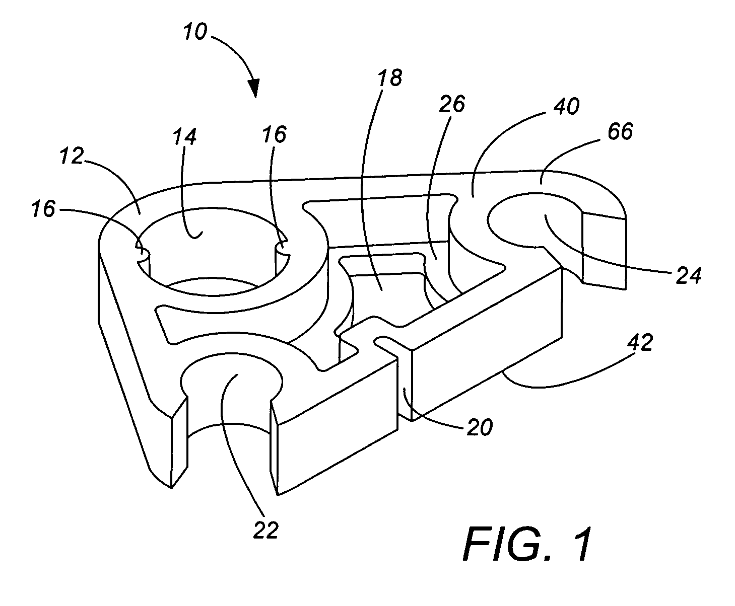
[0029]The present invention will be described with reference to an exemplary part 10 shown in FIG. 1. FIG. 1 represents a “cam” part 10 designed by the customer. In part because the cam 10 is custom-designed (i.e., not a staple article of commerce) by or for this particular customer, the cam 10 includes numerous features, none of which have commonly accepted names. For purposes of discussion, we will give names to several of these features, including a part outline flange 12, a circular opening 14 with two rotation pins 16, a non-circular opening 18, a notch 20, two corner holes 22 and 24, and a partial web 26. However, workers skilled in the art will appreciate that the customer may in fact have no name or may have a very different name for any of these features.

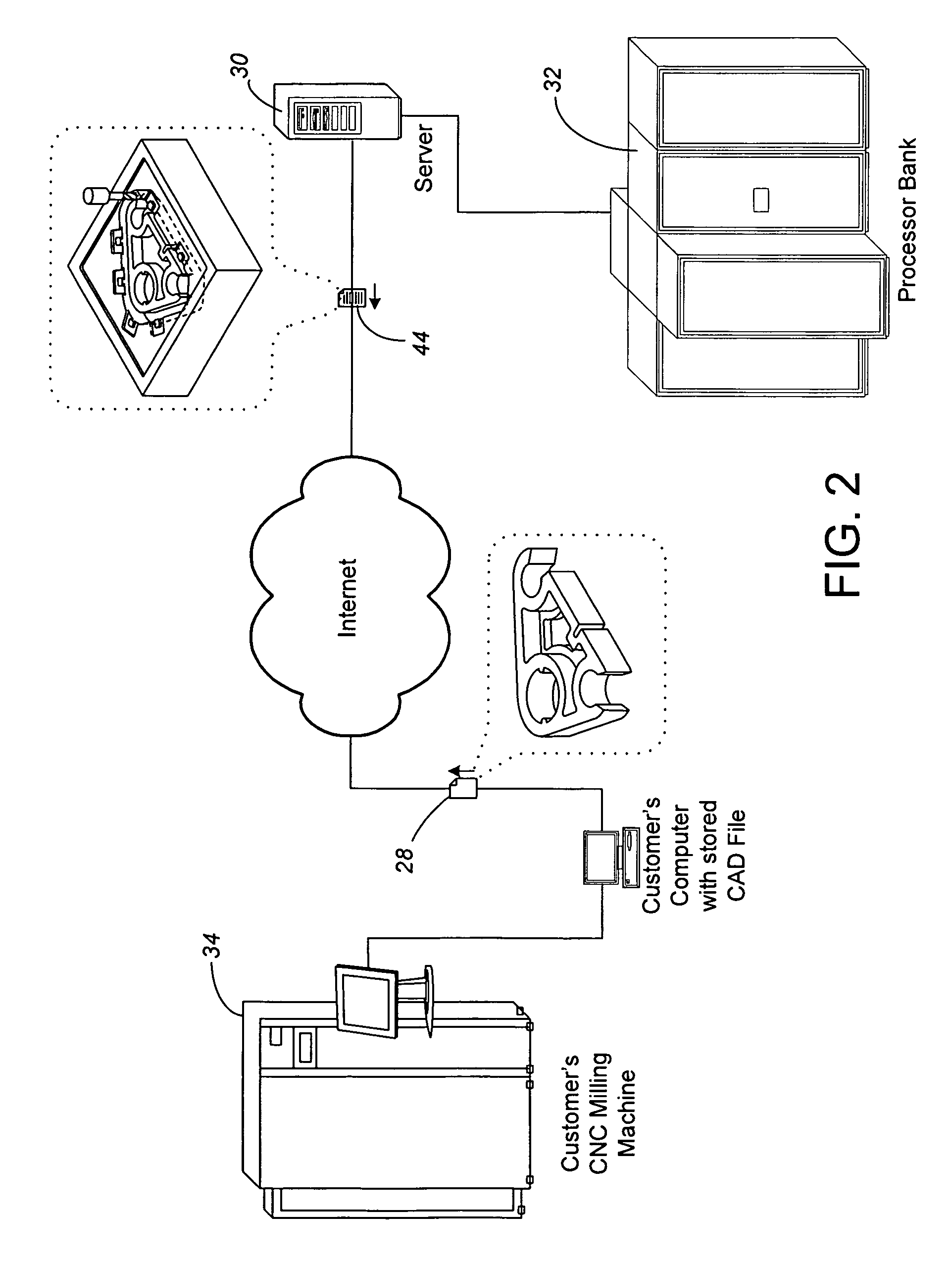
[0030]In the process of the present invention, the customer (most likely the designer of the cam 10) transmits a CAD part data file 28 such as over the internet to a computer system including a server 30. As partially depic...


PUM

PropertyMeasurementUnit
tooling timeaaaaaaaaaa
timeaaaaaaaaaa

Abstract

A customer transmits their 3D CAD file for a part to be total profile machined. Computer analysis of the transmitted CAD file produces CNC machining instructions, which are transmitted back to an address defined by the customer. The customer can then use the transmitted CNC machining instructions to total profile machine their own part using their own CNC mill at the location where the part is likely needed. The transmitted instructions include not only the tool paths for CNC machining of the total profile of the part, but also for additional features formed into the encircling portion of a material block from which the part is to be total profile machined. For instance, the CNC machining instructions transmitted back to the customer can define a registration recess and / or channels or undercuts for fluid support material on an A-side of a material block. After the A-side of the block is machined, the customer adds and solidifies fluid support material into the machined recess. The CNC mill is then used to machine a support surface into a portion of the solidified support material surface. A registration fixture is applied into contact with the support surface CNC machining on the B-side of the material block is then performed while the part is supported by the solidified support material, substantially separating the part from the encircling block of material. The support material is then removed, such as by dissolving, freeing the part from the encircling block of material.

Description

CROSS-REFERENCE TO RELATED APPLICATION(S)[0001]None.BACKGROUND OF THE INVENTION[0002]The present invention relates to the field of prototype or low volume part making, and particularly to total profile machining of parts such as from blocks of plastic materials using CNC machines, wherein a substantial majority of the surface area of the part is created by the CNC machining.[0003]With the quickening pace of product design schedules, the fast turn-around production of low quantity or prototype parts for testing new designs has become more and more common. Product designers need to move from the drawing board (or, in today's world, the computer screen) to having an example product in hand within weeks if not days. To meet these rapid schedules, many designers have turned to the field of rapid prototyping, to quickly convert their written design drawings into a physical part specimen. Most common rapid prototyping techniques are additive processes, wherein material is added in layers o...

Claims


Application Information

Patent Timeline
Patent Type & Authority Patents(United States)
IPC IPC(8): G06F19/00G06F17/50G16Z99/00
CPCB29C33/3835B29C33/3842G06Q30/0283Y10T29/49995Y10T29/49158Y10T29/49146G16Z99/00
Inventor LUKIS, LAWRENCE J.DREIZIN, YURI A.BLOOM, GREGORY M.
Owner PROTOLABS INC
Why Eureka
Try Eureka