Dispensing device for dispensing a product

a technology for dispensing devices and products, applied in the direction of liquid dispensing, angle demodulation, electrical apparatus, etc., can solve the problems of affecting the accuracy of aiming at a target, and prone to instability of hand holding the container and operating the gripper

Inactive Publication Date: 2011-06-14
RUST OLEUM NETHERLANDS
View PDF19 Cites 22 Cited by
  • Summary
  • Abstract
  • Description
  • Claims
  • Application Information

AI Technical Summary

Benefits of technology

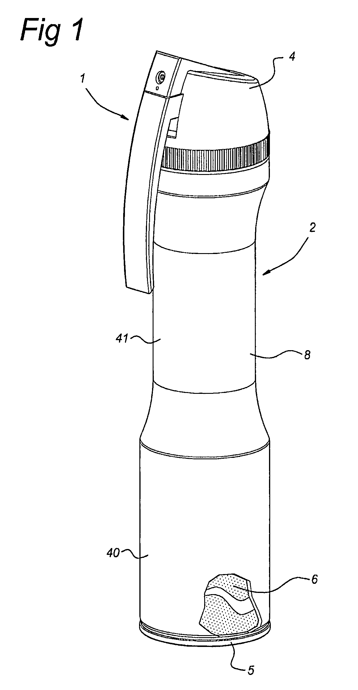
[0010]a dispensing cap mounted on the top of the container.The dispensing cap of the dispensing device according to the invention carries: a nozzle debauching outside the cap for spraying the product, the nozzle being connected to the valve mechanism by a conduit; as well as an actuating member having a horizontal arm and a vertical arm, the horizontal and vertical arm being rigidly connected to each other. The terms vertical and horizontal arm are related to the dispensing device considered in upright standing condition. The vertical arm extends in the axial direction of the container with its free end facing downwards. The horizontal arm is hingedly suspended in the cap and engages the valve mechanism to actuate the valve mechanism upon pulling the vertical arm towards the body portion. The body portion can be seen as divided into a lower portion and an upper portion, the upper portion of the body portion comprising a one-hand grip. The “upper portion comprising a one-hand grip” is to be understood as dimensioned so that the dispensing device can be held by one-hand gripping around the one-hand grip provided at the upper portion of the body portion of the container. In order to be able to operate the actuating member with the same hand, the vertical arm is arranged to be engagable by at least one finger of the hand gripping the one-hand grip. According to the invention the one-hand grip is in its circumference constricted with respect to the lower portion. This means that the circumference of the upper portion is smaller than the circumference of the lower portion and that consequently the lower portion has a volume per axial length—of the container—unit which is larger than the volume per axial length unit of the upper portion. By configuring the container body in this manner, the centre of gravity of the dispensing device is—considered with respect to prior art devices having a container of the same volume—shifted downwards towards the bottom of the container without increasing the axial length of container being required. The device is thus easy to handle. Assuming that during dispensing the top of the container is directed upwards—which is for this kind of dispensing devices advisable—this means that the hand holding and actuating the dispensing device can be held more stable. A dispensing device which is easier held stable enables a more accurate aiming of the nozzle at the target.
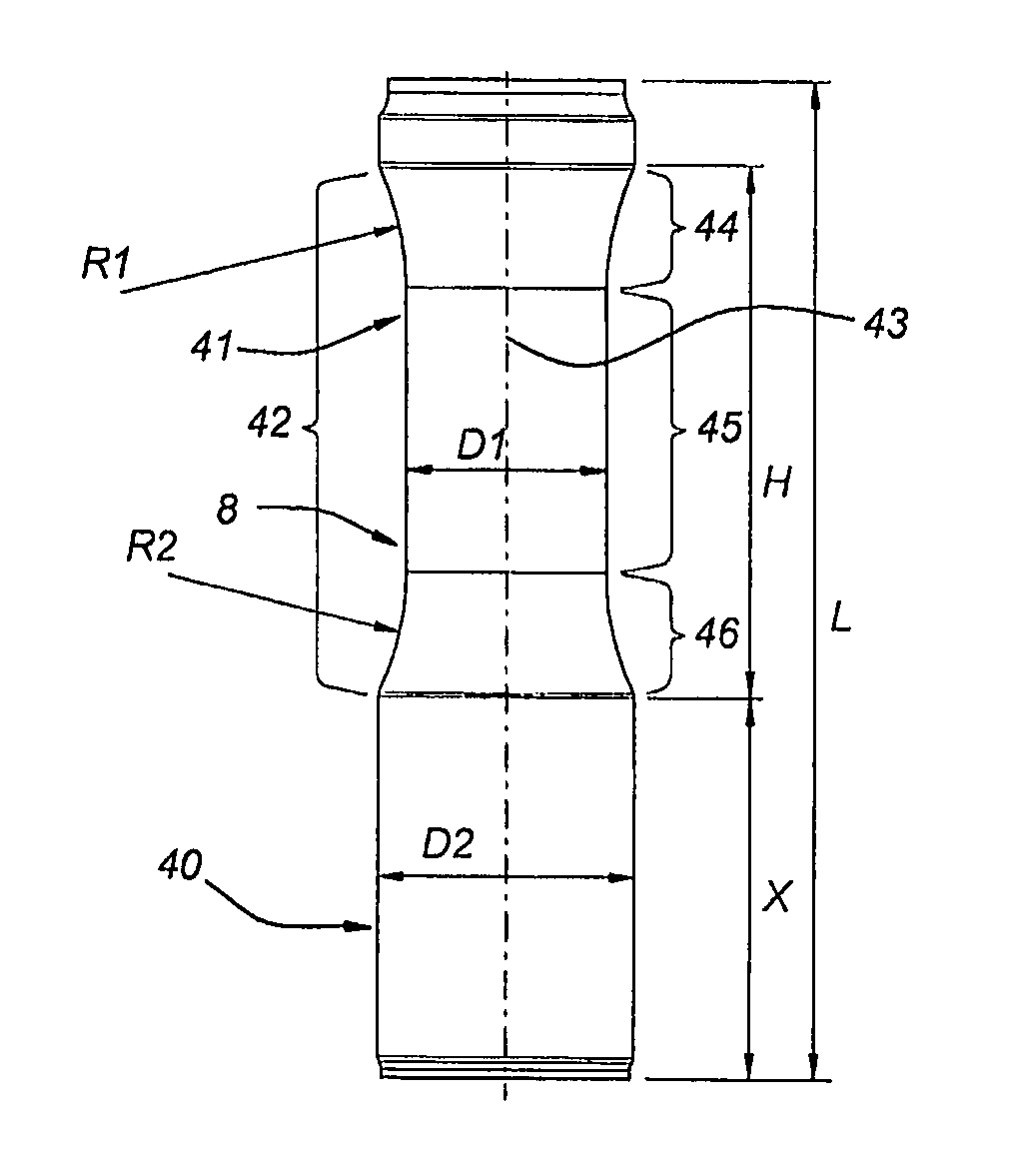
[0011]The holding stability and thus the accuracy of aiming at a target can be further improved when the upper end of the one hand grip widens with respect to the centre of the one-hand grip to provide a supporting surface adapted for resting on the upper part of a hand gripping around the one-hand grip. The widening of the upper and of the one hand grip following, viewed in the axial direction, a continuous curvature, provides this advantage that the dispensing device lies more comfortable in the hand, which contributes in the aiming accuracy. This comfort is improved when the continuous curvature has a radius between 55 and 75 mm, preferably between 60 and 72 mm. The comfort of use is further improved when the lower end of the one-hand grip also widens with respect to the centre of the one-hand grip to provide a supporting surface, in this case adapted for supporting the lower part of a hand gripping around the one-hand grip. Also in this case it is advantageous when this widening of the lower end of the one-hand grip follows, viewed in the axial direction, a continuous curvature. Preferably this continuous curvature at the lower end of the one-hand grip has a radius between 55 and 75 mm, preferably between 60 and 72 mm. The lower end of the one-hand grip and the upper hand of the one-hand grip can thus be shaped mirror symmetrically.
[0013]According to the invention it is further advantageous when the circumference of the centre of the one-hand grip is at most 190 mm, preferably at most 180 mm, more preferably at most 170 mm. A circumference of at most 190 mm, corresponding to a circle diameter of about 60-61 mm, provides a one-hand grip, which can be held good by a male hand of above average size, and which can also be held by a male hand of average size. A circumference of at most 180 mm, corresponding to a circle diameter of about 57 mm, provides a one-hand grip which can be held very solidly by a male hand of above average size, and which can be held good by a male hand of average size. A circumference of at most 170 mm, corresponding to circle diameter of about 54-55 mm, provides a solid grip for a male hand of average size.
[0016]According to a further advantageous embodiment of the invention, the nozzle is fixed with respect to the cap. A nozzle fixed with respect to the cap prevents the nozzle from moving together with the actuating member, which would make aiming of the nozzle at the target less accurate.
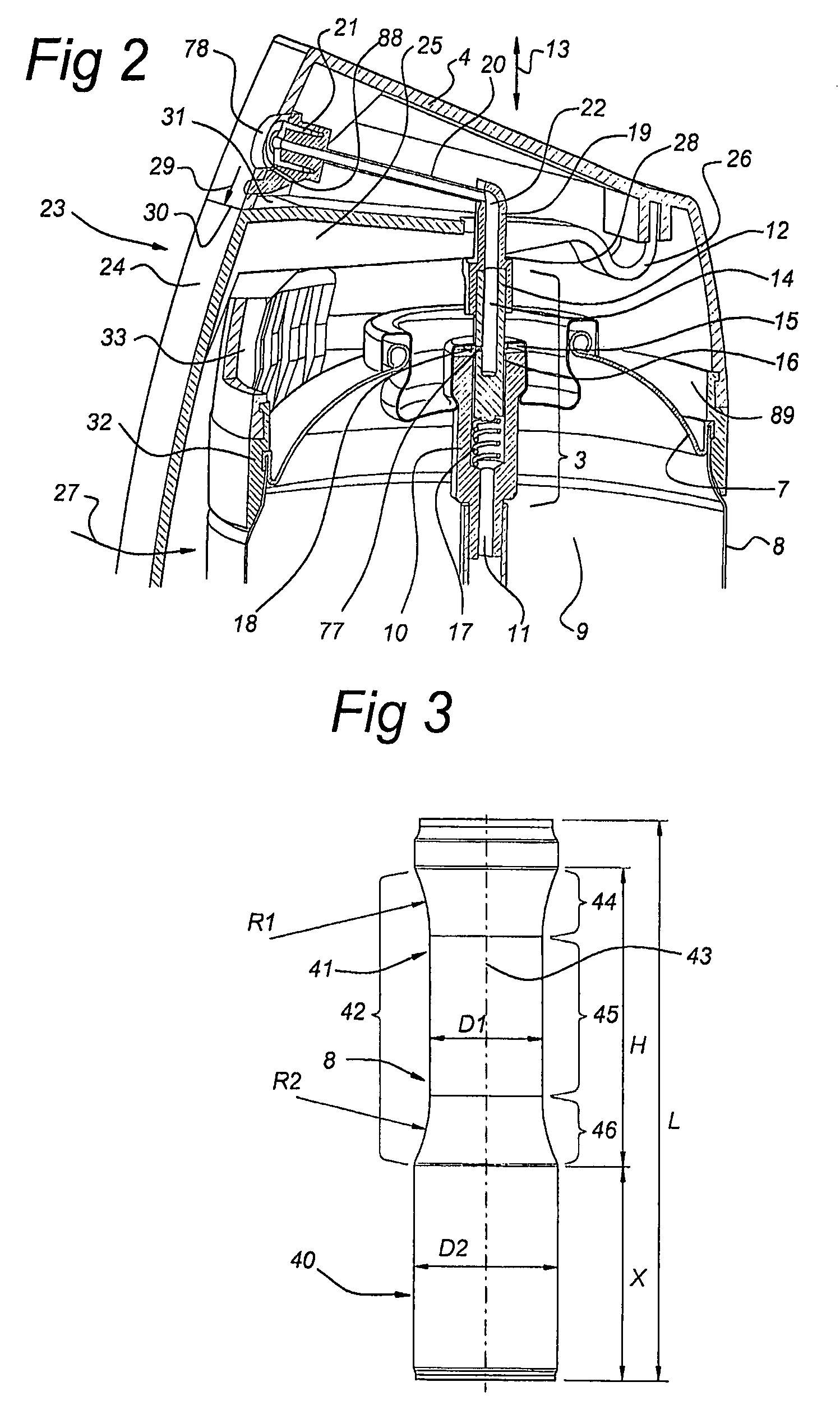
[0017]According to a further embodiment of the invention, the vertical arm of the actuating member is arranged essentially below the nozzle. Arranging the vertical arm essentially below the nozzle enables accurately aiming the nozzle at the target. A further advantage is that drips of products originating from the nozzle can be collected on the horizontal arm—not only when the device is held upright but also when the device is held in a slanting position—. Drips collected on the horizontal arm can—when the device is held upright—be guided into the cap so that the user is prevented from contacting. In this respect it is of additional advantage when the horizontal arm projects from the cap. In this respect it is to be noted that only a slight projection of about 0.5 mm is sufficient. According to a further advantageous embodiment, which optionally can advantageously be applied with the vertical and / or horizontal arm arranged essentially below the nozzle, the nozzle is arranged submerged in a recess formed in the cap. A submerged arrangement of the nozzle in the cap provides collection means for small drips coming out of the nozzle at the start or at end of a spraying action. The submerged recess will provide for retainment of the small drips in the recess so that the hand of the user is prevented from contacting the drips. Advantageously the recess containing the submerged nozzle will be in liquid communication with the hollow internal of the cap, so that drips of product, such as paint, can flow into the cap where they do not harm. The hands of the user are thus being protected against becoming dirty.
[0019]In order to prevent inadvertently spraying, the container is, at its top, provided with a stop and the actuating member is around the axial direction rotatable with respect to the stop between a locked position in which the stop lies under the horizontal arm of the actuating member to prevent movement of the actuating member and an unlocked position in which the stop lies beside the actuating member to allow movement of the actuating member. By rotating the stop and the actuating member with respect to each other, one can prevent the actuating member from any movement as well as allow actuating of the actuating member.

Problems solved by technology

A disadvantage of this type of dispensing device is that the accuracy in aiming at a target is influenced by the stability of the hand holding the device.
Not withstanding that such a trigger type operated dispensing device is believed to promise a better aiming accuracy then the general type device in which a button is pressed in axial direction of the container by a finger, the hand holding the container and operating the gripper appears to be susceptible for instability when aiming at the target.

Method used


Image

  • Dispensing device for dispensing a product
  • Dispensing device for dispensing a product
  • Dispensing device for dispensing a product

Examples


Embodiment Construction

[0025]The dispensing device 1 according to the present invention comprises a container 2, a conventional valve mechanism 3 and a dispensing cap 4.

[0026]The container 2 has a bottom 5, a top 7 and body portion 8. The bottom 5, top 7 and body portion 8 are, in a manner conventional, secured to each other to define an airtight inner volume 9. The inner volume 9 contains product 6 to be dispensed.

[0027]A conventional valve mechanism 3 is provided on the top 7 of the container 2. Briefly described, this conventional valve mechanism 3 comprises a fixed part 10 having a through going bore 11. The fixed part 10 is fixed in an airtight manner to the top 7 of the container. The bore 11 has an upper part of larger diameter. In this upper part there is provided a pin 12 with a blind bore 14. The pin 12 being movable up and down, according to arrow 13. Below the pin 12 there is provided a spring 17 urging the pin 12 in the upward direction. The blind bore 14 has at its lower side a side bore 77,...


PUM


Abstract

The invention relates to a dispensing device (1) for dispensing a product. The dispensing device comprises: a container (2) containing the product under pressure, the container having a top (7), bottom (5) and body portion (8), an axial direction being defined between the bottom and top; a valve mechanism (3) mounted at the top of the container, the valve mechanism being movable with respect to the container for pressurized discharge of the product out of the container; and a dispensing cap (4) mounted on the top of the container. The dispensing cap carries: a nozzle (21) debouching outside the cap for spraying the product, the nozzle being connected to the valve mechanism by a conduit; and art actuating member (23) having a horizontal arm (25) and a vertical arm (24). The horizontal arm is hingedly suspended in the cap and engages the valve mechanism to actuate the valve mechanism upon pulling the vertical arm towards the container portion. The body portion of the container has a lower portion (40) and an upper portion (41) providing a one-band grip (42). The vertical arm is arranged to be engageable by at least one finger of a hand gripping the one-band grip. The one-hand grip is constricted in its circumference with respect to the lower portion.

Description

FIELD OF THE INVENTION[0001]The invention relates to a dispensing device for dispensing a product. The dispensing device being of the type comprising a container containing the product under pressure and a valve mechanism mounted at the top of the container, which valve mechanism is movable with respect to the container for pressurised discharge of the product out of the container.BACKGROUND OF THE INVENTION[0002]Dispensing devices of the type to which the invention relates are known for long. Such dispensing device can for example have pressurized containers of the aerosol type, in which the container contains the product to be dispensed as well as a pressurising fluid. The dispensed product can for example be paint, oil, such as lubrication oil, insecticide, deodorant, hairspray, wood and furniture polish etc. It is known that also many other types of product are dispensed with such dispensing devices.[0003]In general the valve mechanism is mounted at the top of the container and ...

Claims


Application Information

Patent Timeline
Patent Type & Authority Patents(United States)
IPC IPC(8): B65D83/00B65D83/14B65D83/16
CPCB65D83/206B65D83/201
Inventor HEIRMAN, BJORN BORIS IGOR
Owner RUST OLEUM NETHERLANDS
Why Eureka
Try Eureka