Particle radiation therapy equipment

a radiation therapy equipment and particle technology, applied in the field of particle radiation therapy equipment, can solve the problems of large number of present mri scanners that are not suitable, and achieve the effect of improving radiation therapy efficiency and reducing radiation therapy intensity

Inactive Publication Date: 2011-06-14
SIEMENS HEALTHCARE LTD
View PDF11 Cites 53 Cited by
  • Summary
  • Abstract
  • Description
  • Claims
  • Application Information

AI Technical Summary

Benefits of technology

[0014]The present invention accordingly provides apparatus and methods as set out in the appended claims.

Problems solved by technology

This may result in the irradiation of healthy tissue and or missing diseased tissue, which may lead to a remission.
The majority of present MRI scanners are not suitable for this because the beam would be obstructed by the cryostat.

Method used


Image

  • Particle radiation therapy equipment
  • Particle radiation therapy equipment
  • Particle radiation therapy equipment

Examples


Embodiment Construction

[0028]The present invention provides an application of the magnet coil arrangement described in WO 02 / 065149 as a means of monitoring the target area for radiation therapy during application of a charged particle beam.

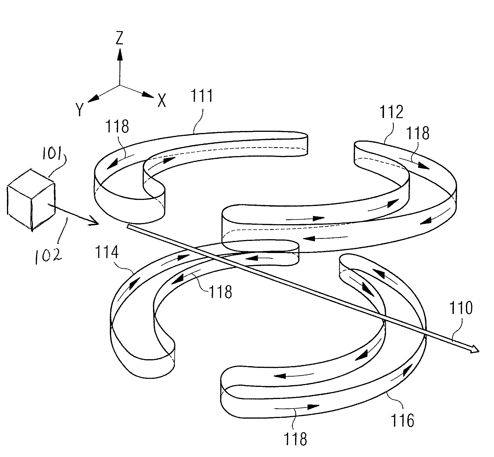
[0029]Advantageously, and according to the present invention, such coil arrangements are arranged such that the magnetic field they produce lies in the intended direction 110 of application of a particle beam 102 for particle radiation therapy. Since application of the beam of charged particles will be in the direction of the magnetic field, the beam will not be deflected, and a dose of particle radiation may be accurately applied to the intended target.

[0030]Examples of such arrangements will now be described with reference to FIGS. 1-12.

[0031]FIG. 1 shows an arrangement consisting of four coils 111, 112, 114, 116 and a XYZ co-ordinate reference frame, which will be referred to in the following description. The coils 111-116 shown in FIG. 1 are symmetrically arranged ...


PUM


Abstract

Particle radiation therapy equipment arranged to apply a charged particle beam in a predetermined direction to a region of application within an imaging volume, comprising a charged particle beam source arranged to direct a charged particle beam in the predetermined direction, further comprising magnetic field generation means for generating a magnetic field in the region of application at the same time that the charged particle beam is applied, wherein the magnetic field generation means is arranged to provide access to the region of application for the charged particle beam, and to provide a homogeneous magnetic field in the region of application of the charged particle beam, said magnetic field being directed substantially in the predetermined direction.

Description

CROSS-REFERENCE TO RELATED APPLICATIONS[0001]This application is related to co-pending U.S. patent application Ser. No. 11 / 917,959 filed concurrently herewith.FIELD OF THE INVENTION[0002]The present invention describes particle radiation therapy equipment which includes a magnet, thereby enabling magnetic resonance imaging (MRI) during particle radiation therapy.BACKGROUND OF THE INVENTION[0003]Radiation therapy with protons and carbon ion beams has been shown to be effective. In addition it has been shown to result in less damage to tissue than conventional gamma radiation therapy.[0004]However, radiation planning for determining the magnitude and position of a dose to be administered is based on MRI imaging or CT imaging, which may have taken place at a considerable time period before the therapy takes place. In the intervening period, the position of the tissue to be irradiated may have moved, or changed shape. This may result in the irradiation of healthy tissue and or missing d...

Claims


Application Information

Patent Timeline
Patent Type & Authority Patents(United States)
IPC IPC(8): A61B5/05A61B5/055A61N5/10G01R33/38
CPCA61N5/1049G01R33/3806A61B5/055A61N2005/1055A61N2005/1087A61N5/1067G01R33/48
Inventor KRUIP, MARCEL JAN MARIEBEASLEY, PAUL
Owner SIEMENS HEALTHCARE LTD
Why Eureka
Try Eureka