Networkable LED-based lighting fixtures and methods for powering and controlling same

a led-based lighting and network technology, applied in the direction of electric controllers, electric programme control, instruments, etc., can solve the problems of time-consuming and error-prone setting switches, cumbersome process, and inability to configure lighting networks in many hours, so as to improve the durability of lighting units and simplify installation.

Active Publication Date: 2011-06-14
PHILIPS LIGHTING NORTH AMERICA CORPORATION
View PDF149 Cites 102 Cited by
  • Summary
  • Abstract
  • Description
  • Claims
  • Application Information

AI Technical Summary

Problems solved by technology

Settings switches tends to be time consuming and error prone.
These devices have to be individually set to particular addresses and this process can be cumbersome.
Not surprisingly, the configuration of a lighting network can take many hours, depending on the location and complexity.
Mix-ups and confusion are common during this process.
With sufficient planning and coordination this address selection and setting can be done a priori but still requires substantial time and effort.
There are several other disadvantages associated with these lighting systems, particularly with those designed for direct view applications.
Conventional lighting networks, however, often produce little or no light in the gaps between adjoining fixtures, which tend to detract from the intended appearance of these installations.
In addition, because each of the components is addressed individually, the degree of coordination of the lighting effects, i.e. “resolution” of the application, is limited to the size of the components.
For example, in a linear installation having a number of 1-foot long components, the components cannot be addressed any finer than in 1-foot increments.
Also, another disadvantage of these systems is that when the LEDs are directly viewed they appear to be discrete light emitters until there is sufficient distance between the light and the viewer.
Even when the viewer is relatively far away from the lighting system, the lighting system does not tend to produce very bright or clearly perceivable lighting effects.
Mounting of the fixtures is very expensive and cumbersome because it is implemented through junction boxes.

Method used


Image

  • Networkable LED-based lighting fixtures and methods for powering and controlling same
  • Networkable LED-based lighting fixtures and methods for powering and controlling same
  • Networkable LED-based lighting fixtures and methods for powering and controlling same

Examples


Embodiment Construction

[0064]Various embodiments of the present invention are described below, including certain embodiments relating particularly to LED-based light sources. It should be appreciated, however, that the present disclosure is not limited to any particular manner of implementation, and that the various embodiments discussed explicitly herein are primarily for purposes of illustration. For example, the various concepts discussed herein may be suitably implemented in a variety of environments involving LED-based light sources, other types of light sources not including LEDs, environments that involve both LEDs and other types of light sources in combination, and environments that involve non-lighting-related devices alone or in combination with various types of light sources.

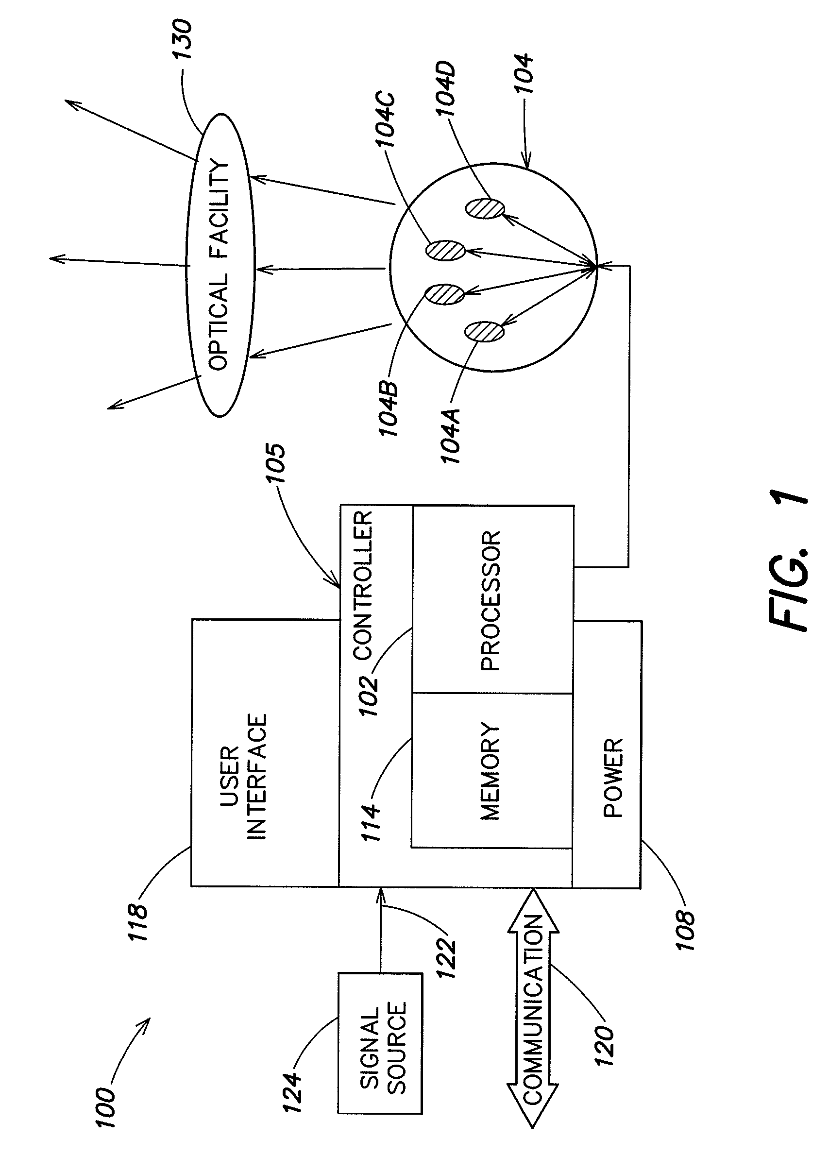
[0065]FIG. 1 illustrates one example of a lighting unit 100 according to one embodiment of the present invention. Some general examples of LED-based lighting units similar to those that are described below in connection wi...


PUM


Abstract

A lighting fixture, and methods for powering and operating same. The fixture comprises a housing having multiple portions. One or more power and control circuit boards are disposed in a first portion of the housing, comprising one or more switching power supplies for receiving an A.C. line voltage and providing a D.C. output voltage, and a communication protocol converter for receiving first lighting instructions formatted according to a first communication protocol and converting at least some of the first lighting instructions to second lighting instructions formatted according to a second communication protocol. A plurality of modular circuit boards are disposed in the second portion of the housing and coupled to the power and control circuit board(s). Each modular circuit board comprises a plurality of LED-based lighting units coupled to the D.C. output voltage and responsive to the second lighting instructions formatted according to the second communication protocol.

Description

CROSS-REFERENCE TO RELATED APPLICATION[0001]The present application claims the benefit, under 35 U.S.C. §119(e), of U.S. Provisional Application Ser. No. 60 / 862,183, filed Oct. 19, 2006, entitled “Lighting Fixtures Comprising Multiple Lighting Units and Methods for Powering And Controlling Thereof,” which provisional application is hereby incorporated herein by reference.BACKGROUND[0002]The advent of digital lighting technologies, i.e. illumination based on semiconductor light sources, such as light-emitting diodes (LEDs), offers a viable alternative to traditional fluorescent, HID, and incandescent lamps. Functional advantages and benefits of LEDs include high energy conversion and optical efficiency, robustness, lower operating costs, and many others. The LEDs' smaller size, long operating life, low energy consumption, and durability make them a great choice in a variety of lighting applications. For example, it is becoming increasingly popular to create lighting networks of LED-b...

Claims


Application Information

Patent Timeline
Patent Type & Authority Patents(United States)
IPC IPC(8): G05B19/02H05B44/00
CPCH05B33/0842H05B37/0254H05B33/0857H05B45/00H05B45/20H05B47/18H05B45/33H05B45/355H05B45/325H05B45/3725Y02B20/30H05B47/155
Inventor RABINER, MARK D.SHIKH, IGORLOGAN, DEREKHART, BILLROBERGE, BRIAN
Owner PHILIPS LIGHTING NORTH AMERICA CORPORATION
Why Eureka
Try Eureka