Electric energy control circuit for solar power illumination system

a solar power and control circuit technology, applied in secondary cells servicing/maintenance, lighting and heating apparatuses, instruments, etc., can solve the problems of long sunlight exposure time of many public illumination devices, shorten the life of batteries, and public safety problems, so as to reduce the bad weather-induced attrition of solar power illumination systems, prolong the power supply time of batteries, and reduce the effect of bad weather-induced attrition

Inactive Publication Date: 2011-06-21
KING POLYTECHNIC ENG
View PDF3 Cites 7 Cited by
  • Summary
  • Abstract
  • Description
  • Claims
  • Application Information

AI Technical Summary

Benefits of technology

[0003]One objective of the present invention is to provide a control circuit, which modulates the power output in the lamp-lighting interval according to the power generation of solar panels to reduce the bad weather-induced attrition of a solar power illumination system and solves the problem that weather affects the lifetime of a conventional solar power illumination system outputting a fixed power in the fixed lamp-lighting interval preset by a timer.
[0004]The present invention discloses an electric energy control circuit for a solar power illumination system. The solar power illumination system has at least one solar panel coupled to a charging controller, and the solar panel charges at least one battery via the charging controller. The electric energy control circuit of the present invention controls a driving unit to acquire electric energy from the battery and turn on at least one lamp set. The electric energy control circuit comprises: a power detection loop and an output control loop. The power detection loop is coupled to the solar panel and the battery and generates a power generation signal and a remaining capacity signal according to the power generation of the solar panel and the remaining capacity of the battery. The output control loop is coupled to the power detection loop to receive the power generation signal and the remaining capacity signal and determines the power output to the lamp set according to the power generation signal and the remaining capacity signal. The power control loop has a time-setting mode controlling the lamp-lighting interval and a power-distribution mode having different power output ratios within a fixed lamp-lighting interval. The output control loop generates a driving signal under the time-setting mode or the power-distribution mode to actuate the driving unit, and the driving unit converts the power from the battery into a driving power to turn on the lamp set. Via the abovementioned circuit architecture, the present invention modulates the output power according to the power generation and the remaining capacity, makes the solar power illumination system have different working modes, and adjusts the power of solar power illumination system according to the weather. Thus, the present invention can prolong the power supply time of the battery and reduce the bad weather-induced attrition of the solar power illumination system.

Problems solved by technology

Many public illumination devices are long time radiated by sunlight.
However, the abovementioned design has the intrinsic problem of solar energy.
When the weather is unfavorable during daytime, solar panels absorb solar energy lower than the designed value, but the batteries still have to release energy to lamps at night.
If there is a bad weather lasting for several successive days, the remaining battery capacity will persistently decrease, which may cause incapability of lighting lamps or interruption of lamp illumination and thus induce the problem of public security.
Besides, the persistent low battery remaining capacity caused by a long-term bad weather will shorten the lifetime of batteries, which will obviously increase the repair and maintenance expense.
At present, the conventional solar energy illumination devices still lack an effective solution for the abovementioned problems, which consumes budgets and impairs the popularization thereof.

Method used


Image

  • Electric energy control circuit for solar power illumination system
  • Electric energy control circuit for solar power illumination system
  • Electric energy control circuit for solar power illumination system

Examples


Embodiment Construction

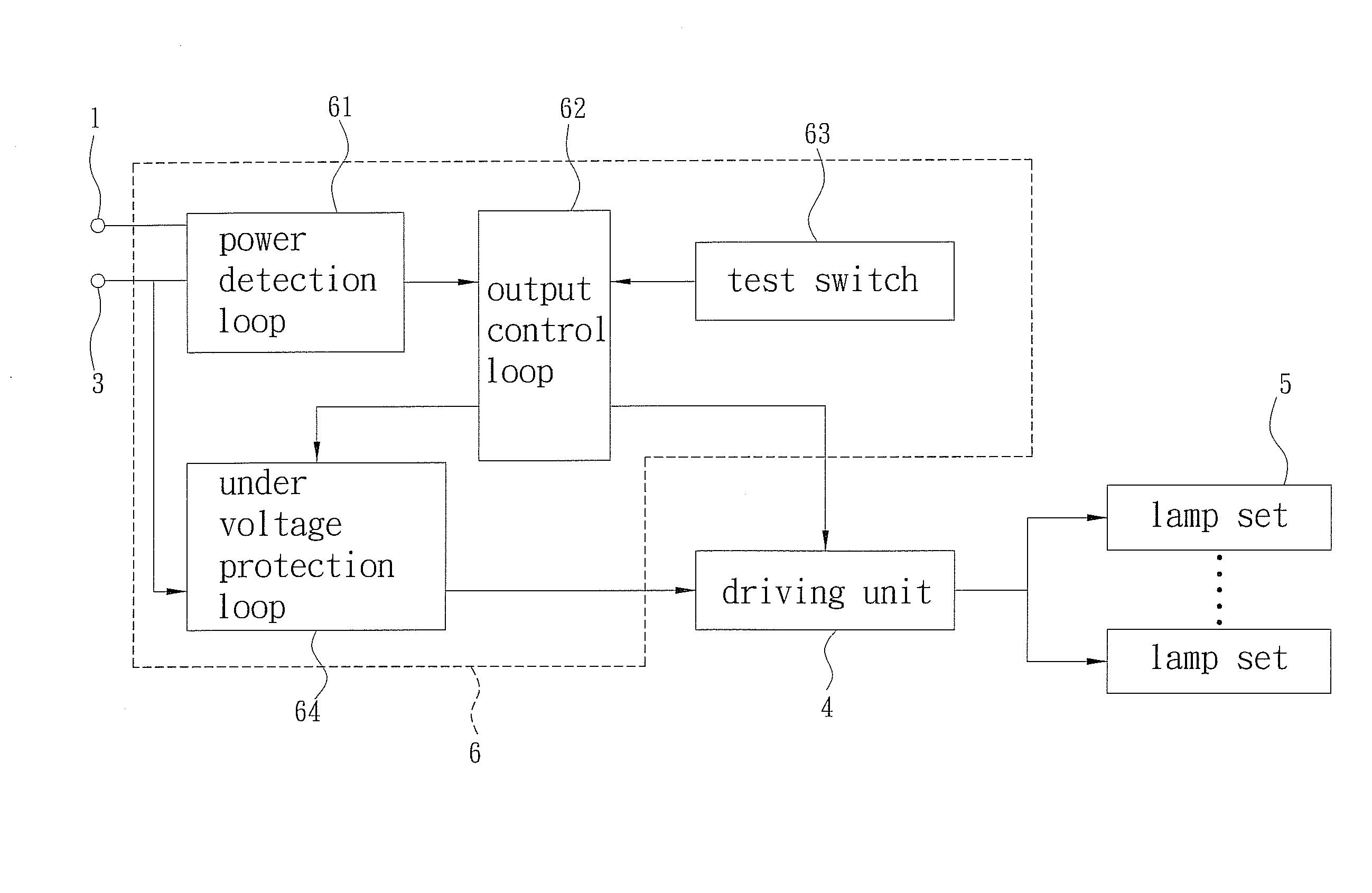
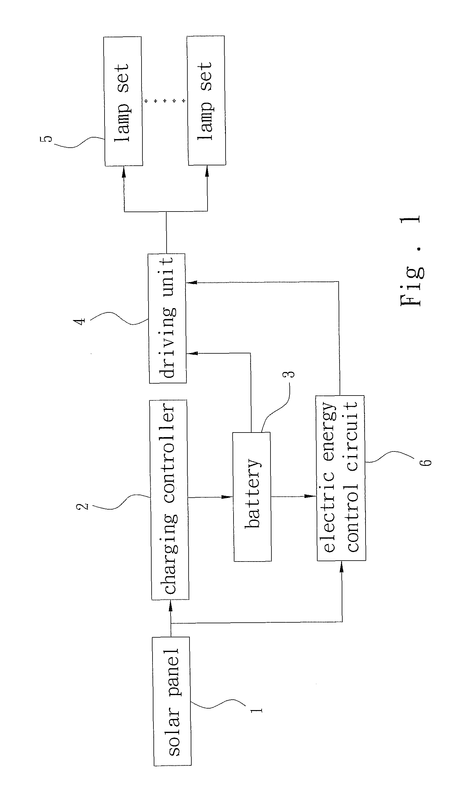
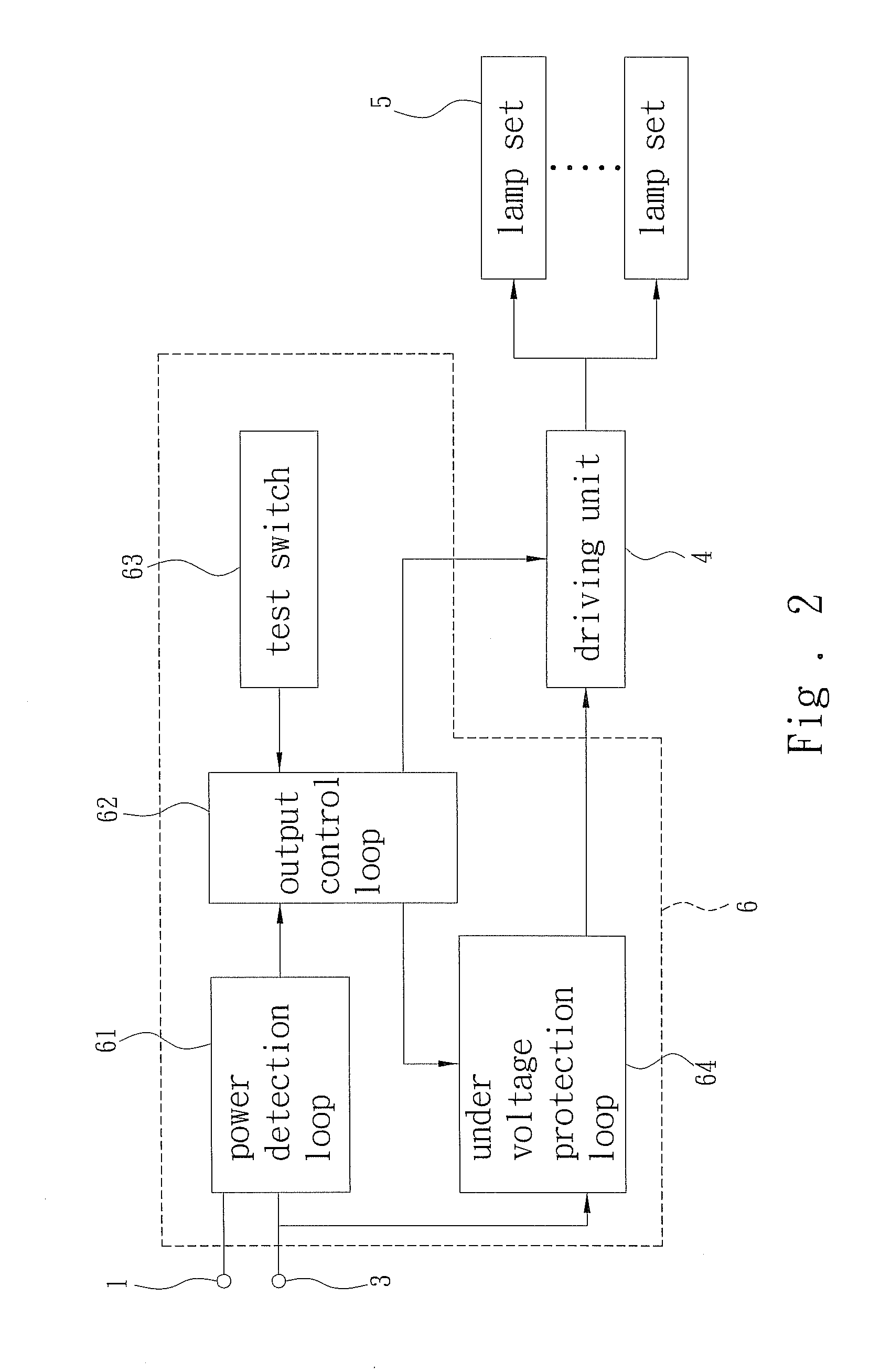
[0008]Refer to FIG. 1 and FIG. 2. The present invention discloses an electric energy control circuit for a solar power illumination system. The solar power illumination system has at least one solar panel 1 coupled to a charging controller 2, and the solar panel 1 charges at least one battery 13 via the charging controller 2. An electric energy control circuit 6 according to the present invention controls a driving unit 4 to acquire electric energy from the battery 3 and turn on at least one lamp set 5. As shown in FIG. 2, the electric energy control circuit 6 comprises: a power detection loop 61 and an output control loop 62. The power detection loop 61 is coupled to the solar panel 1 and the battery 3 and generates a power generation signal and a remaining capacity signal according to the power generation of the solar panel 1 and the remaining capacity of the battery 3. The output control loop 62 is coupled to the power detection loop 61 to receive the power generation signal and ...


PUM


Abstract

The present invention discloses an electric energy control circuit for a solar power illumination system. The solar power illumination system has at least one solar panel coupled to a charging controller, and the solar panel charges at least one battery via the charging controller. An electric energy control circuit according to the present invention controls a driving unit to acquire electric energy from the battery and turn on at least one lamp set. The electric energy control circuit comprises: a power detection loop and an output control loop. The power detection loop is coupled to the solar panel and the battery and detects the power generation of the solar panel and the remaining capacity of the battery. The output control loop is coupled to the power detection loop and determines the power output to the lamp set according to the power generation and the remaining capacity. Thereby, the present invention can modulate the power for the solar power illumination system according to the weather, prolong the power supply time of the battery, and reduce the bad weather-induced attrition of the solar power illumination system.

Description

FIELD OF THE INVENTION[0001]The present invention relates to an electric energy control circuit for a solar power illumination system, particularly to a circuit, which evaluates the remaining battery capacity and modulates the power for lamps in a solar power illumination system.BACKGROUND OF THE INVENTION[0002]In the age of energy shortage and environmentalism, solar energy has been an important substitute energy, and solar panels usually cooperate with high capacity batteries to achieve flexible solar energy application. Many public illumination devices are long time radiated by sunlight. If they are powered by solar energy, considerable electric power will be saved. In solar energy powered illumination devices, batteries store the electric energy, which is converted from solar energy, and timers turn on lamps using electric energy after sunset / turn off lamps to store electric energy after sunrise. Thereby, the solar energy powered illumination devices store energy during daytime ...

Claims


Application Information

Patent Timeline
Patent Type & Authority Patents(United States)
IPC IPC(8): H05B41/36
CPCH02J7/35Y10S323/906
Inventor CHOU, HENG-YI
Owner KING POLYTECHNIC ENG
Why Eureka
Try Eureka