Display system, screen design setting tool, display system program, screen design setting program, and recording medium

a display system and screen design technology, applied in the field of display system, screen design setting tool, display system program, screen design setting program, etc., can solve the problems of increasing the number of required graphics display controllers and the cost of the entire display system, and achieve the effect of reducing cost and high degree of freedom of screen layou

Inactive Publication Date: 2011-06-21
SHARP KK
View PDF9 Cites 15 Cited by
  • Summary
  • Abstract
  • Description
  • Claims
  • Application Information

AI Technical Summary

Benefits of technology

[0007]In order to overcome the problems described above, preferred embodiments of the present invention provide a display system, which can be mounted in a mobile object and has high degrees of freedom for screen layout, and has a lower cost.
[0009]According to the above configuration, the combination image division section cuts out individual item images as independent image blocks from the single combination image; and the display data generation section freely lays out each of the image blocks, so as to generate display data. Consequently, without modifying (e.g., adding a GDC) an image generating section (in other words, with the cost being curbed), the degrees of freedom for screen layout can be increased. Furthermore, according to the above configuration, it is possible that at first, a plurality of item images be inputted as the single image closely composed thereof, and then divided and freely laid out. Therefore, the size of the data to be transmitted and inputted can be decreased, compared to a configuration in which individual item images are laid out first, and then transmitted and inputted. Consequently, efficiency of data processing can be enhanced and hardware can be downsized.
[0010]According to the present display system, the display data generation section preferably arranges the individual image blocks in predetermined forms and positions. This can further increase the degrees of freedom for screen layout.
[0011]In addition, according to the present display system, the display data generation section may lay out the image blocks based on screen layout data determining forms and positions thereof. Thus, in a case that the screen layout data is configured to be optionally set up by a user (vehicle manufacturers and drivers), the user will freely set up a preferred screen, and therefore will become more satisfied. Besides, the screen layout data may also be set up based on a condition of the moving object. As a result, a driver can acquire adequate information based on the condition of the moving object, and be more satisfied.
[0019]As described above, according to the display system of various preferred embodiments of the present invention, the combination image division section cuts out individual item images as independent images from a single combination image; and the display data generation section freely lays out each of the item images so as to generate display data. Consequently, without modifying (adding a GDC, etc.) the image generating section (in other words, with the cost being curbed), the degrees of freedom for screen layout can be increased.

Problems solved by technology

However, as the number of images to be displayed and data sizes thereof have increased recently, the number of required graphics display controllers has increased; higher processing capacities have been required; and input systems have become more complex, all of which have led to an issue that the cost of the entire display system significantly increases.

Method used


Image

  • Display system, screen design setting tool, display system program, screen design setting program, and recording medium
  • Display system, screen design setting tool, display system program, screen design setting program, and recording medium
  • Display system, screen design setting tool, display system program, screen design setting program, and recording medium

Examples


Embodiment Construction

[0040]Preferred embodiments of the present invention are described below with reference to FIGS. 1 to 7.

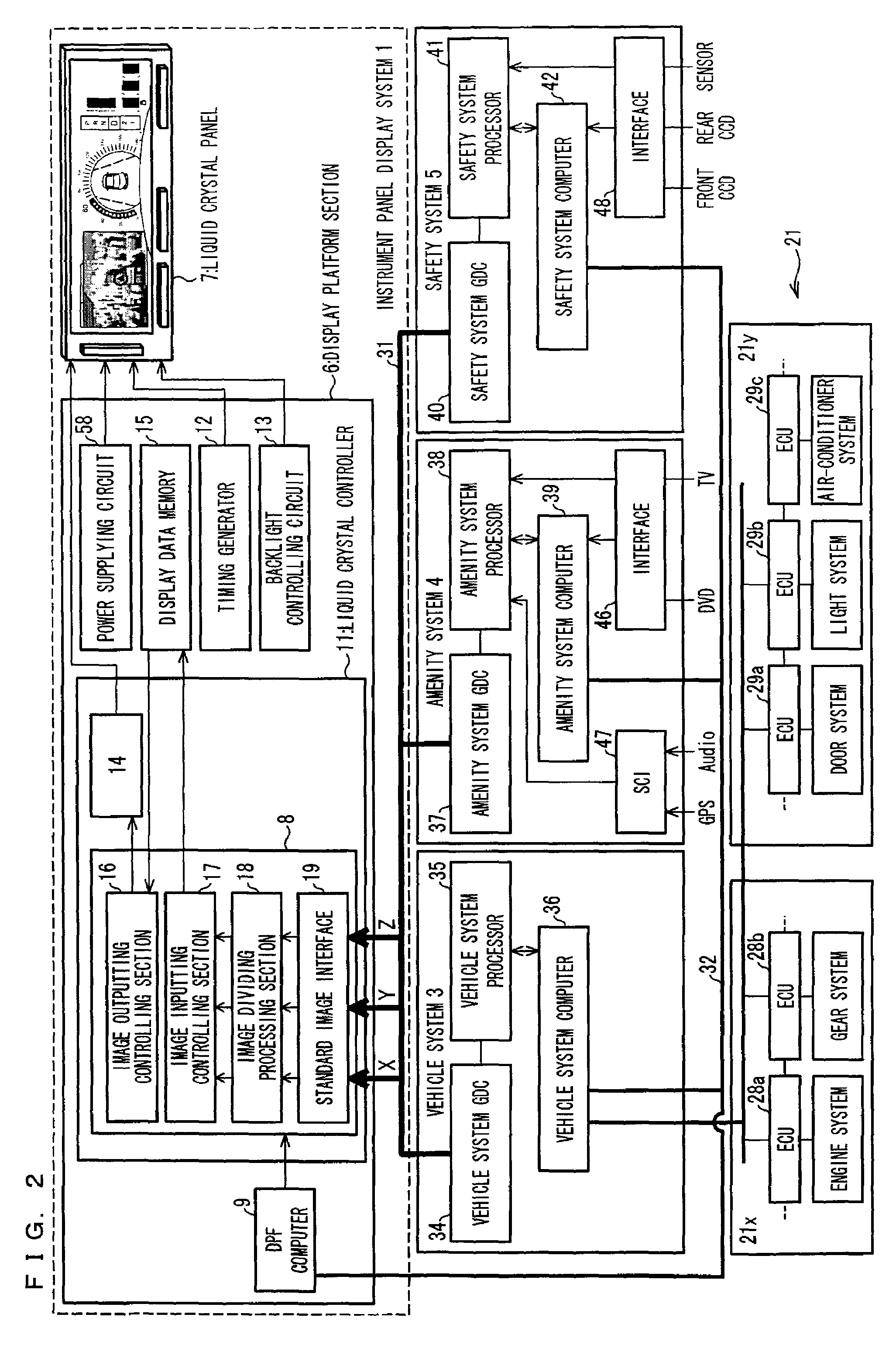
[0041]FIG. 2 is a block diagram illustrating an instrument panel control system of the present preferred embodiment. As FIG. 2 illustrates, the present instrument panel control system includes an instrument panel display system 1, an input / output system of an amenity system (an amenity system 4) for amenity content such as DVD, TV, GPS, Audio and the like, an input / output system of a safety system (a safety system 5) for safety content such as various types of CCD and a sensor, and an in-car LAN 21 for transmitting vehicle data. The in-car LAN 21 includes a power train system in-car LAN 21x and a body system in-car LAN 21y. To the power train system in-car LAN 21x, an electric controlling unit (ECU) 28a for controlling an engine system, an electric controlling unit (ECU) 28b for controlling a gear system, etc., are connected. Furthermore, to the body system in-car LAN 21y, an elec...


PUM


Abstract

A display system includes a combination image dividing section arranged to divide a single combination image composed of a plurality of item images into a plurality of image blocks such that each of the image blocks has an item image; an image inputting controlling section arranged to lay out the individual image blocks; and an image inputting controlling section arranged to generate display data based on the image blocks laid out thereby. This can achieve a display system, to be mounted in the maneuverable moving object and having high degrees of freedom for screen layout, at a lower cost.

Description

BACKGROUND OF THE INVENTION[0001]1. Field of the Invention[0002]The present invention relates to a display system (e.g., a display system for use with an instrument panel) mounted on a moving object (such as a vehicle), which is maneuverable.[0003]2. Description of the Related Art[0004]Recently, a display system that displays, on a display (a display section), an image in addition to images of vehicle information including a traveling speed and engine rotation frequencies has been proposed as a display system mounted in an instrument panel of an automobile or the like. The image additionally displayed on the display system may be an image of navigation, TV, or DVD or an image captured by a camera (CCD) mounted on a vehicle. High degrees of freedom for screen layout are required of those display systems such that vehicle safety can be increased by displaying, based on a vehicle condition, necessary information in an easily viewable manner or such that users' (vehicle manufacturers an...

Claims


Application Information

Patent Timeline
Patent Type & Authority Patents(United States)
IPC IPC(8): G09F9/00G09F9/30B60Q1/00G08B3/00
CPCB60K35/00B60K37/02G09G5/14G09G2340/12B60K2350/901B60K2370/736
Inventor KOBAYASHI, MASAKIFUJIMOTO, FUMIAKIOKAMOTO, TOSHIYAAOKI, TOSHIYA
Owner SHARP KK
Why Eureka
Try Eureka