Image forming apparatus with dehumidifying heater

a technology of dehumidification heater and forming apparatus, which is applied in the direction of electrographic process apparatus, instruments, optics, etc., can solve the problems of difficult to prevent the scattering of waste toner, pollute the circumference, and insufficiently so as to save costs, prevent the spread of waste toner, and facilitate maintenance

Active Publication Date: 2011-06-21
KONICA MINOLTA BUSINESS TECH INC
View PDF7 Cites 1 Cited by
  • Summary
  • Abstract
  • Description
  • Claims
  • Application Information

AI Technical Summary

Benefits of technology

[0013]The present invention was conceived in view of the above-mentioned situation, and an object of the invention is to provide an image forming apparatus capable of preventing dirt of sheets caused by the scattering of toner and not lowering the fluidity of waste toner with heat of a dehumidifying heater at the time of waste toner recovery.
[0025]With the above structures, it becomes possible to prevent waste toner scattered from the waste toner box from entering into the sheet tray, whereby the dirt of sheets can be prevented. Moreover, it can be prevented that heat of the dehumidifying heater transfer to the waste toner box, whereby the hardening of waste toner in the vicinity of the waste toner box due to the heat can be prevented. As a result, the fluidity of waste toner to be recovered to the waste toner box can be maintained, and waste toner can be recovered to the waste toner box smoothly without the adhesion of the waste toner onto the conveying passage.
[0026]With the above structures, when the above partition member is structured so as to constitute a part of reinforcing members to reinforce a body of the apparatus, the strength for the space to arrange the sheet tray and the waste toner box can be maintained without adding another reinforcing member, thereby saving costs.
[0027]With the above structures, that is, when the waste toner box is arranged at the upstream side of the sheet tray in the sheet feeding direction and the partition member is arranged between the waste toner box and the sheet tray and between the dehumidifying heater and the waste toner box, a space for a maintenance work can be secured in the sheet feeding passage, thereby conducting maintenance easily.

Problems solved by technology

In the above-mentioned structures, at the time of attaching or detaching the above-mentioned waste toner box, when a discharging port of a conveying passage to convey waste toner from the cleaning member to the waste toner box is separated from a joint port of the waste toner box, there has been problems that waste toner scatters from the discharging port and the joint port and pollutes the circumference.
However, it is difficult to prevent waste toner from scattering to the circumference and it is not sufficient to prevent dirt of sheets.
In Patent document 2, it is unable to draw waste toner adhering to a discharging port into the conveying section, and it is not sufficient to prevent scattering of waste toner.
As mentioned above, it is unable to say that it is enough to prevent scattering of waste toner, and also it is unable to say that it is enough to prevent dirt of sheets.
As a result, the hardened waste toner interferes the fluidity of waste toner at the time of waste toner recovery and makes it difficult to recover waste toner.

Method used


Image

  • Image forming apparatus with dehumidifying heater
  • Image forming apparatus with dehumidifying heater
  • Image forming apparatus with dehumidifying heater

Examples


Embodiment Construction

[0032]An embodiment of an image forming apparatus according to the present invention will be described with reference to drawings. However, the present invention is not limited to the following embodiment.

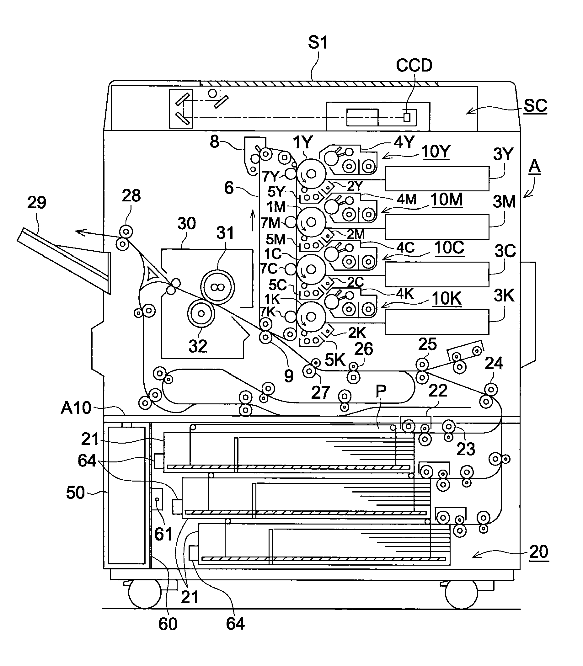
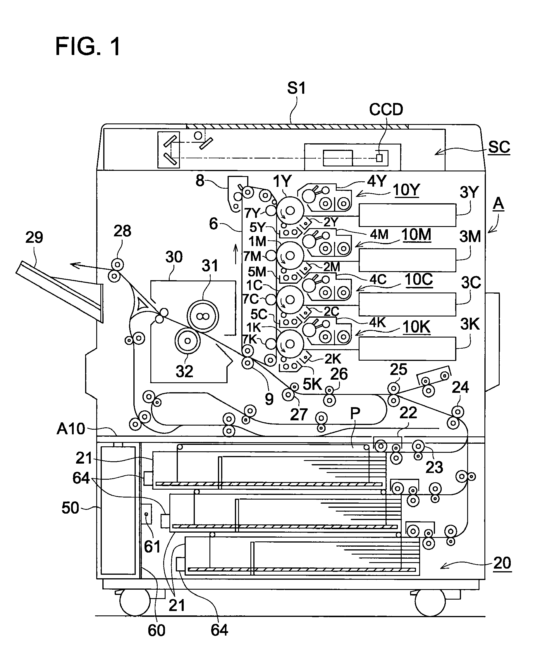
[0033]FIG. 1 is a cross-sectional schematic view showing an example of an image forming apparatus according to the present invention.

[0034]The image forming apparatus according to the present invention comprises an apparatus main part A and an image reading apparatus (hereinafter, referred to as scanner) SC. The apparatus main part A is called a tandem type color image forming apparatus and comprises plural sets of image forming sections 10Y, 10M, 10C, and 10K, a belt-like intermediate transfer member 6, a transferring section 9 being a transferring means, a sheet feeding section 20, and a fixing device 30. The sheet feeding section 20 is also used as a sheet tray accommodating section.

[0035]A scanner SC is installed in the upper part of the apparatus main part A. An image on a doc...


PUM


Abstract

An image forming apparatus includes an image carrying member; an image forming section to form a toner image on the image carrying member; a transferring section to transfer the toner image formed on the image carrying member to a sheet; a fixing section to fix the toner image onto the sheet; a sheet feeding section to feed a sheet to the transferring section; a sheet tray to store sheets to be fed by the sheet feeding section; a dehumidifying heater arranged to the sheet tray and to perform dehumidification for sheets; a waste toner box arranged to adjoin the sheet tray and to accommodate waste toner; and a partition member arranged between the sheet tray and the waste toner box and between the dehumidifying heater and the waste toner box.

Description

[0001]This application is based on Japanese Patent Application No. 2007-218179 filed on Aug. 24, 2007 in Japanese Patent Office, the entire content of which is hereby incorporated by reference.BACKGROUND OF THE INVENTION[0002]The present invention relates to an image forming apparatus, such as a copying machine, a printer, and a facsimile, in particular to a waste toner box and a sheet tray in detail.[0003]Conventionally, in the image forming apparatus which has a series of electronic photograph processes, toner remaining on an image carrying member is removed by a cleaning member, such as a cleaning blade, and is accommodated in a waste toner box provided under the cleaning member. Moreover, in order to reduce a dead space in an apparatus and to make a maintenance work easy, it has been well known to structure the apparatus such that a waste toner box is arranged to adjoin beside a sheet tray accommodating section, and the sheet tray and the waste toner box are attached or detached...

Claims


Application Information

Patent Timeline
Patent Type & Authority Patents(United States)
IPC IPC(8): G03G21/12
CPCG03G15/6502G03G21/12G03G2215/00383
Inventor KAWAMOTO, MOTOJI
Owner KONICA MINOLTA BUSINESS TECH INC
Why Eureka
Try Eureka