Eureka AIR delivers breakthrough ideas for toughest innovation challenges, trusted by R&D personnel around the world.

Laser surveying system

a laser surveying and laser technology, applied in the field of laser surveying systems, can solve the problems of complicated system arrangement and high cost, and achieve the effects of reducing gain, easy recognition, and facilitating measurement operation

Active Publication Date: 2011-06-28
KK TOPCON
View PDF14 Cites 15 Cited by
  • Summary
  • Abstract
  • Description
  • Claims
  • Application Information

AI Technical Summary

Benefits of technology

[0010]It is an object of the present invention to provide a laser surveying system, by which it is possible to measure three-dimensional data on an object to be measured.

Problems solved by technology

As a result, the arrangement of the system is complicated and costly.

Method used


Image

  • Laser surveying system
  • Laser surveying system
  • Laser surveying system

Examples


Embodiment Construction

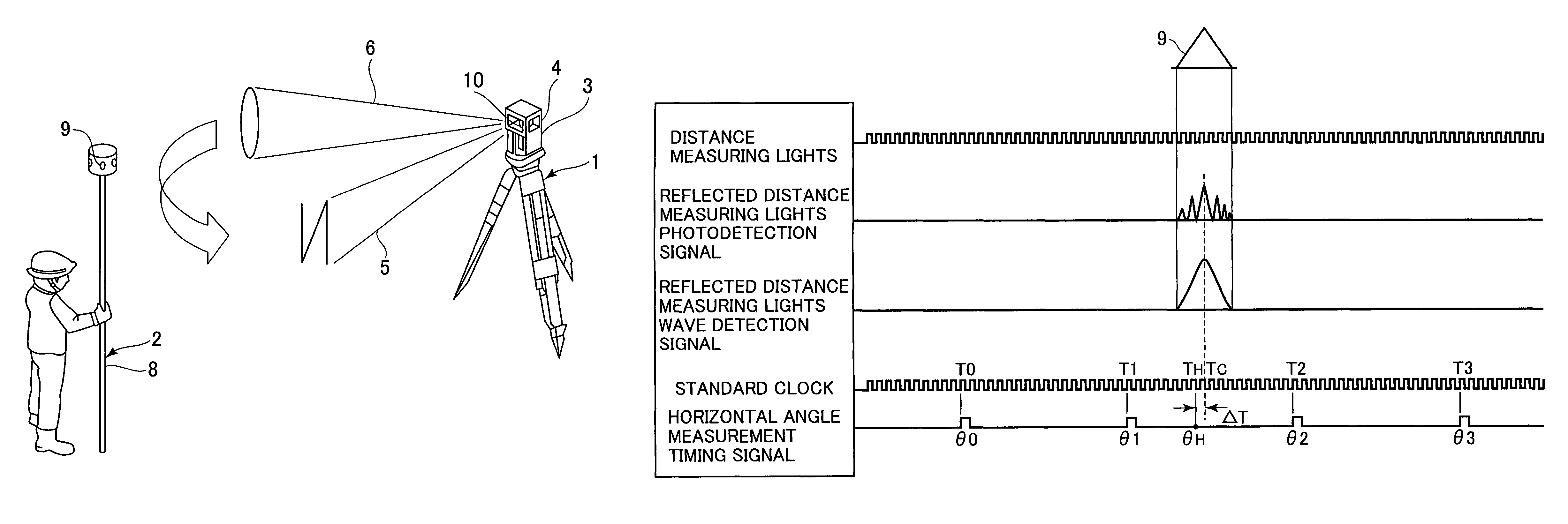
[0029]Description will be given below on the best mode for carrying out the invention by referring to the attached drawings.

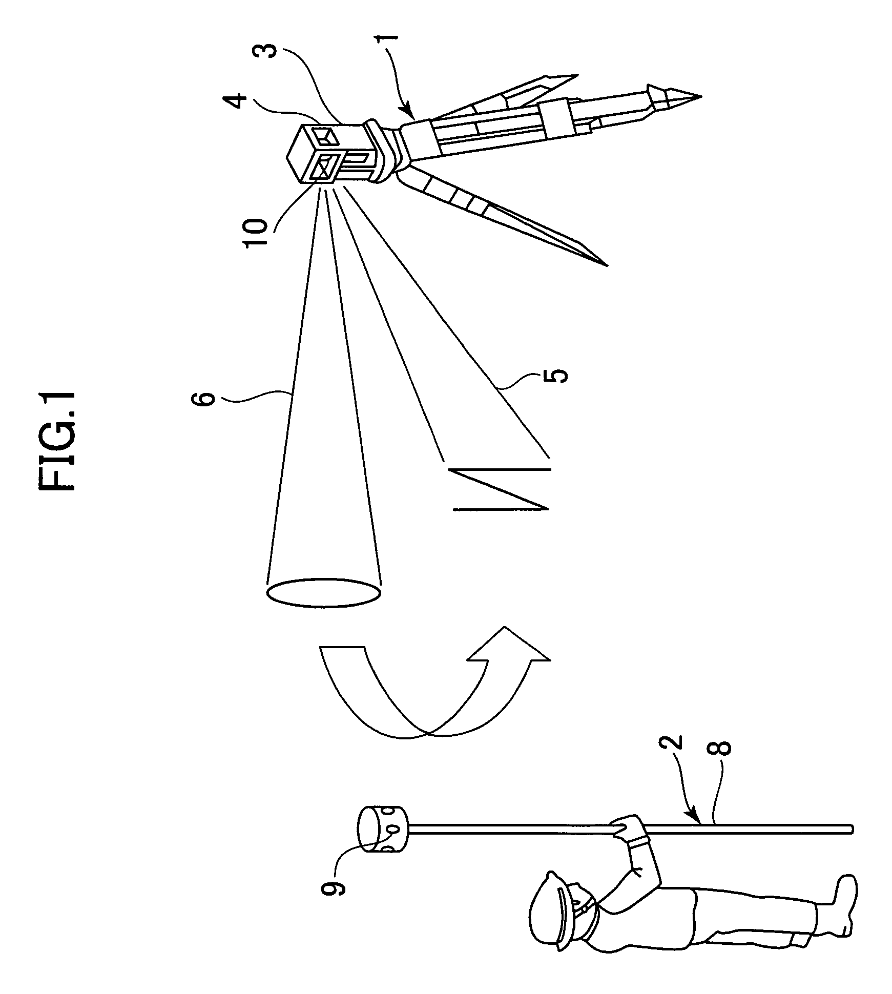
[0030]First, referring to FIG. 1, description will be given on approximate arrangement of the present invention.

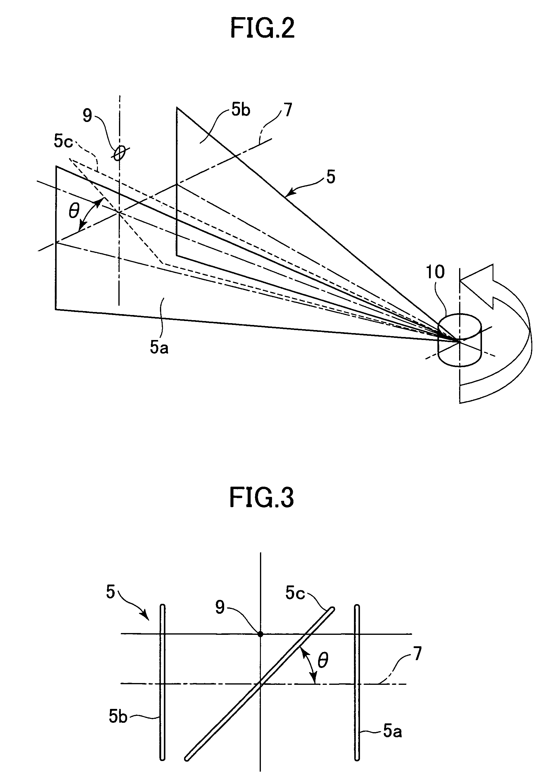
[0031]The laser surveying system according to the present invention comprises a rotary laser projecting device 1 used as a measuring device and an object to be measured 2. the rotary laser projecting device 1 projects two or more fan-shaped laser beams 5, which are continuous scanning light beams,—preferably three fan-shaped laser beams, of which two laser beams at both peripheral ends are perpendicularly with respect to the horizontal plane and a central beam are tilted at a predetermined tilt angle with respect to the horizontal plane, and these three laser beams are combined together in N-shaped form. The rotary laser projecting device 1 also projects a distance measuring light 6, i.e. pulsed light, by rotary irradiation.

[0032]The object to be meas...


PUM


Abstract

A rotary laser projecting device comprising a reference plane forming unit that projects two or more fan-shaped laser beams, a distance measuring unit that projects distance measuring light, a rotator for projecting the fan-shaped laser beams and the distance measuring light by rotary irradiation, a horizontal angle detecting unit, a photodetection unit for receiving the reflected fan-shaped laser beams and the reflected distance measuring light, a storage unit, and a control arithmetic unit is disclosed. The control arithmetic unit measures elevation angle of the object reflector from time difference of photodetection between the two or more laser beams, measures horizontal angle of the object based on the result of detection of the horizontal angle detecting unit when at least one of the reflected fan-shaped laser beams and the reflected distance measuring light is received and the distance measuring unit measures a distance to the object to be measured.

Description

BACKGROUND OF THE INVENTION[0001]The present invention relates to a laser surveying system for projecting laser beams by rotary irradiation and for performing measurement on an object to be measured.[0002]A type of laser surveying system is already known, which performs a distance measurement by projecting a distance measuring light by rotary irradiation, and detects horizontal angle and elevation angle by projecting two or more fan-shaped laser beams with at least one of the beams tilted by rotary irradiation, and measures three-dimensional data.[0003]The laser surveying system as described above comprises a measuring device and a photodetection device. The measuring device projects distance measuring light and fan-shaped laser beams by rotary irradiation, measures a distance to the object to be measured by receiving reflected distance measuring light from the object to be measured, also obtains horizontal angle at the moment of photodetection, and transmits the result of measureme...

Claims


Application Information

Patent Timeline
Patent Type & Authority Patents(United States)
IPC IPC(8): G01C15/00G01C3/08
CPCG01C1/02G01S17/42G01C15/004G01C3/00
Inventor KAMIZONO, FUMIHIKOHAYASHI, KUNIHIRO
Owner KK TOPCON
Why Eureka
Eureka Blog
Learn More