
Press mold and method of manufacturing optical element

a technology of optical elements and press molds, which is applied in the field of press molds, can solve the problems of difficult positioning of molding materials, degrading surface accuracy in terms of optical functions, and difficult to place molding materials at the center position of the molding surface of the lower mold, so as to reduce the amount of molding material needed for individual molding, reduce the amount of molding material needed, and reduce the effect of temperature rise and drop

Inactive Publication Date: 2011-06-28
HOYA CORP
View PDF12 Cites 1 Cited by
  • Summary
  • Abstract
  • Description
  • Claims
  • Application Information

AI Technical Summary

Benefits of technology

[0015]This invention has been made under these circumstances and has an object to provide a press mold that allows a molding material to be stably held in the press mold without causing position offset during the molding process, particularly that can prevent slip-off of the molding material placed on a molding surface of a lower mold without providing the elaborate movable members even if the molding surface of the lower mold has a convex surface, and further, that can regulate the horizontal relative position between an upper mold and the lower mold with high accuracy, thereby obtaining an optical element with high eccentricity accuracy, and further provide an optical element manufacturing method using such a press mold.
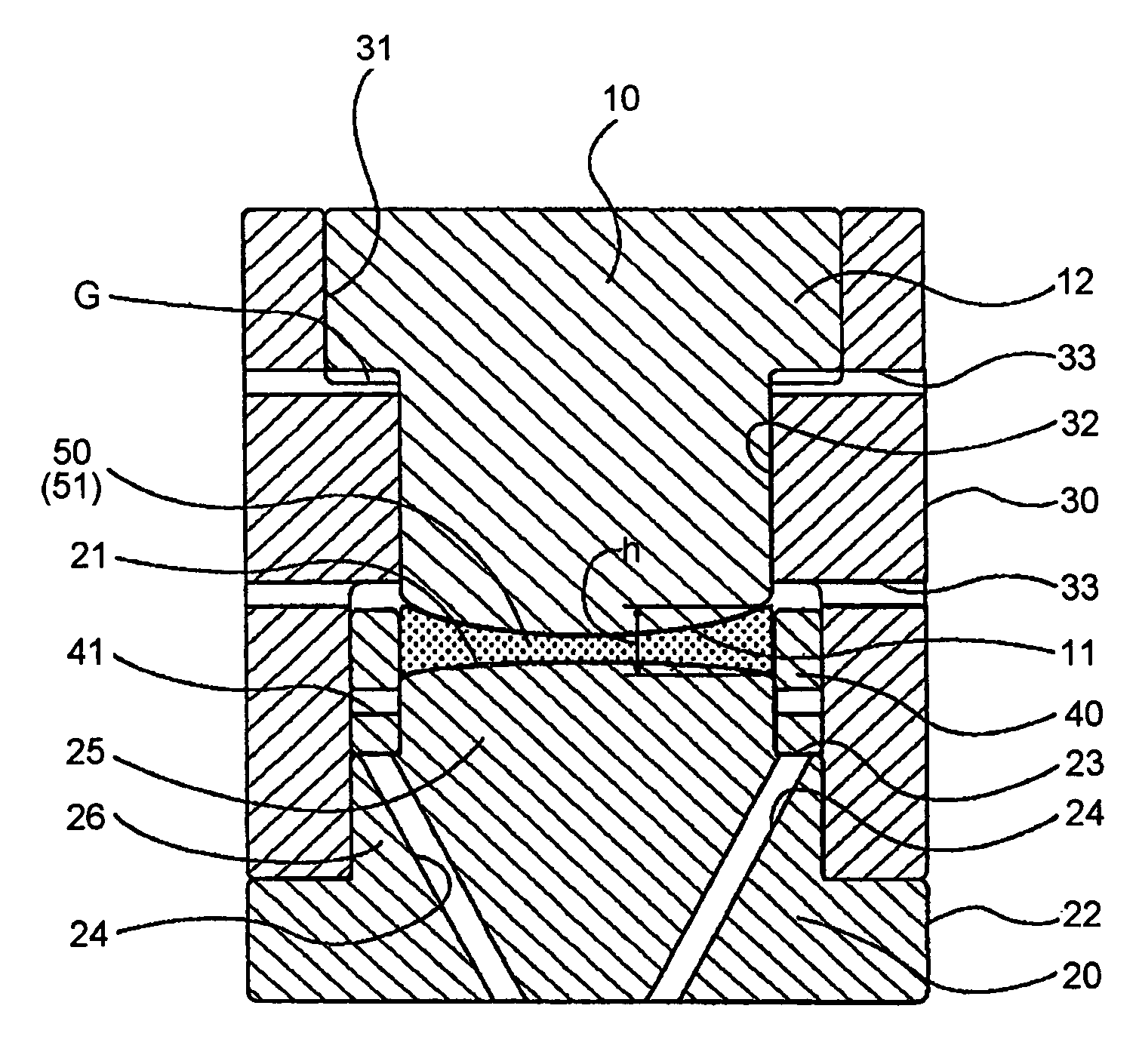
[0016]In order to establish the above object, a press mold according to this invention comprises a lower mold formed with a molding surface, an upper mold formed with a molding surface facing the molding surface of the lower mold, a first sleeve allowing the upper and lower molds to be inserted thereinto from its both end sides, and a second sleeve provided inside the first sleeve. The press mold is adapted to press-mold a molding material between the upper and lower molds. The first sleeve regulates a horizontal relative position between the upper and lower molds. The second sleeve surrounds an outer periphery of the molding surface of the lower mold and supports at least part of an outer peripheral portion of the molding material placed on the molding surface of the lower mold, thereby preventing position offset of the molding material.
[0017]With this configuration, since the second sleeve surrounding the outer periphery of the molding surface of the lower mold supports at least part of the outer peripheral portion of the molding material placed on the molding surface of the lower mold, the position offset of the molding material can be prevented without providing the elaborate movable members.

Problems solved by technology

It is described that, particularly, when molding a double-sided concave lens, the optical material is placed on the lower mold having a convex shape and, therefore, if it is placed in an offset manner, there is a possibility of slipping off the lower mold and thus the positioning of the optical material is required in the press mold.
In this event, it is necessary to supply and place the molding material on the molding surface of the lower mold in advance, but, depending on the shape of the optical element to be obtained, it is not necessarily easy to place the molding material at the center position of the molding surface of the lower mold.
Other than this, positioning of the molding material is difficult when there is no concave surface having a proper curvature at the center area of the molding surface of the lower mold (when the center area of the molding surface of the lower mold is a convex or flat surface).
In those cases, when, for example, the molding material placed on the molding surface of the lower mold is offset in position or slips off at the time of press molding, thickness deviation occurs in the optical material to be molded so that not only shape failure is resulted, but also surface accuracy in terms of the optical function is degraded due to unevenness in load application caused by the thickness deviation.
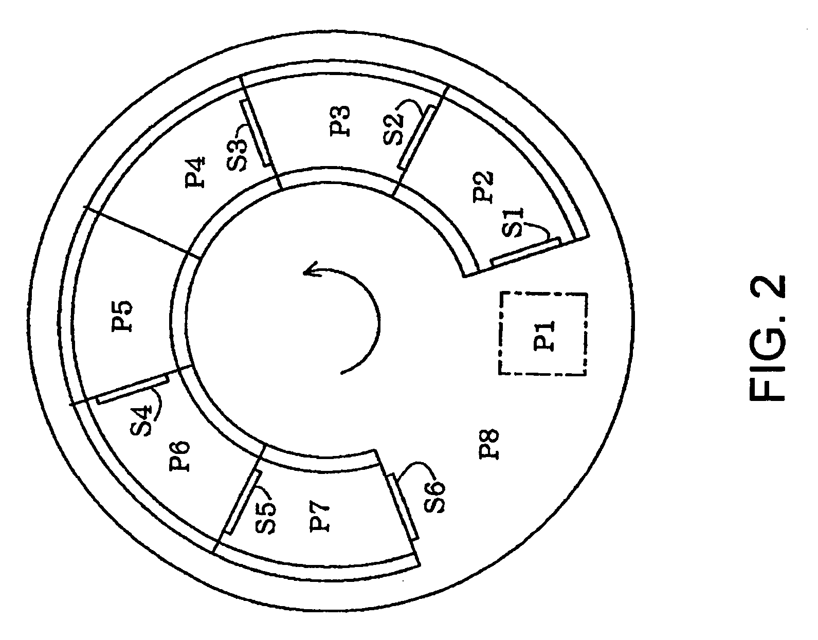
Further, when manufacturing an optical element by transferring a press mold containing a molding material therein to a plurality of process chambers for heating, pressing, cooling, etc. in sequence (details will be described later), the molding material contained in the press mold is subjected to position offset caused by vibration etc. of the press mold during transfer to the respective chambers (particularly upon starting or stopping) and, if molding is carried out while the molding material is offset in position, thickness deviation occurs in the optical material, thus resulting in shape failure.
According to this method, however, since the positioning members are disposed inside the press mold, the structure of the press mold becomes quite complicated.
Consequently, the heat capacity of the press mold increases so that it becomes difficult to efficiently execute a control of temperature rise and drop.
Further, when the structure like the rack-and-pinion drive means is disposed near the press mold, not only a press molding machine increases in size, but also necessity arises to consider the influence of thermal deformation of the structure and so on, so that a machine design is extremely complicated.
However, when manufacturing an optical element by placing a molding material in a press mold separated from a press molding machine and applying proper processes to the press mold in sequence while transferring the press mold in the machine, it is extremely inefficient to provide the foregoing elaborate movable members for each of individual press molds, which is practically impossible.
However, since there is no means for regulating the horizontal relative position between the upper and lower molds, the coaxiality between the upper and lower molds cannot be achieved.
As a result, there occurs eccentricity between the first plane and the second plane (shift between them in the horizontal direction and tilt between them) of a molded optical element so that the sufficiently high optical performance cannot be obtained.

Method used


Image

  • Press mold and method of manufacturing optical element
  • Press mold and method of manufacturing optical element
  • Press mold and method of manufacturing optical element

Examples


Embodiment Construction

[0041]Now, referring to the drawings, description will be made about preferred embodiments of a press mold and an optical element manufacturing method according to this invention.

[Press Mold]

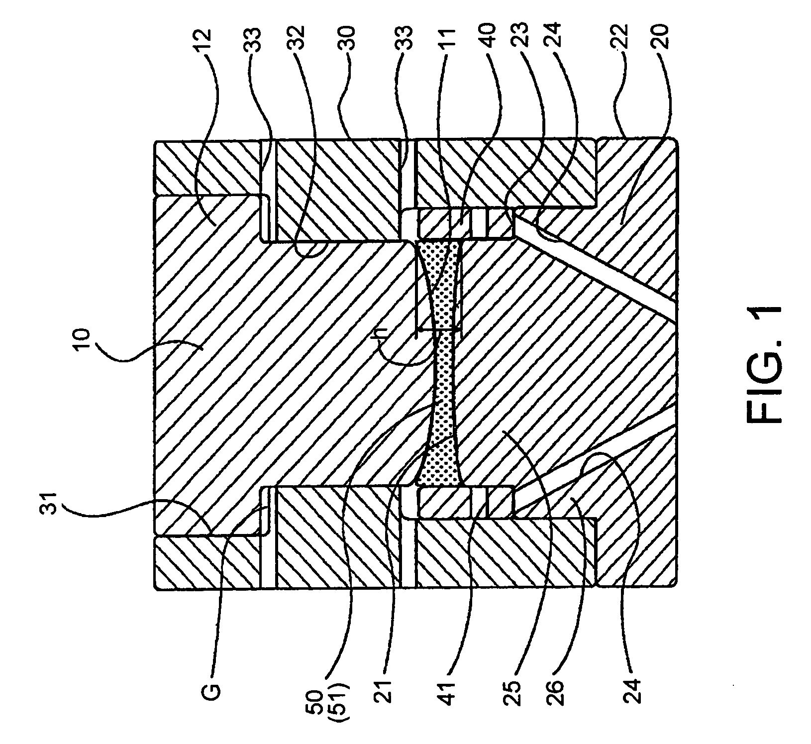
[0042]At first, the embodiment of the press mold according to this invention will be described with reference to FIG. 1. FIG. 1 is a schematic sectional view of the press mold according to this embodiment and shows the state at the time of application of a pressing load (see FIG. 4D, (8)).

[0043]The press mold shown in FIG. 1 comprises an upper mold 10, a lower mold 20, a first sleeve 30, and a second sleeve 40 and is adapted to press-mold a molding material 50 between the upper mold 10 and the lower mold 20.

[0044]In this embodiment, the first sleeve 30 serves to slidingly guide the upper and lower molds 10 and 20 so as to regulate the relative position between them in the horizontal direction at the time of assembly of the press mold and at the time of press molding, thereby ensuring coaxiality ...


PUM

PropertyMeasurementUnit
diameteraaaaaaaaaa
diameteraaaaaaaaaa
thicknessaaaaaaaaaa

Abstract

A first sleeve 30 regulates the horizontal relative position between an upper mold 10 and a lower mold 20 that are insertable into the first sleeve 30 from its both end sides. A second sleeve 40 provided inside the first sleeve 30 and surrounding the outer periphery of a molding surface 21 of the lower mold 20 supports at least part of an outer peripheral portion of a molding material 50 placed on the molding surface 21 of the lower mold 20, thereby preventing position offset and slip-off of the molding material 50. In this state, the molding material 50 is press-molded between the upper mold 10 and the lower mold 20.

Description

[0001]This application claims priority to prior Japanese patent application JP 2005-11989, the disclosure of which is incorporated herein by reference.BACKGROUND OF THE INVENTION[0002]This invention relates to a press mold that is adapted to press-mold a molding material such as a glass by the use of upper and lower molds applied with precision machining and does not require post-processing such as grinding or polishing with respect to a molded surface, and further relates to an optical element manufacturing method using such a press mold.[0003]A method is known where a molding material such as a glass is heated to be softened and then press-molded by a pair of upper and lower molds precisely machined into predetermined shapes, thereby manufacturing an optical element such as a lens [see, e.g. Patent Document 1 (Japanese Patent (JP-B) No. 3501580) and Patent Document 2 (Japanese Unexamined Patent Application Publication (JP-A) No. H09-286622)].[0004]Patent Document 1 describes a mol...

Claims


Application Information

Patent Timeline
Patent Type & Authority Patents(United States)
IPC IPC(8): C03B11/04
CPCC03B11/02C03B11/08C03B2215/47C03B2215/65C03B2215/60C03B2215/61C03B2215/50Y02P40/57A47G29/126
Inventor YAMANAKA, KENJI
Owner HOYA CORP
Learn More