Clutch mechanism applicable to electromechanical cylinders for locks

a technology of electromechanical cylinders and locking mechanisms, applied in the direction of mechanical control devices, keyhole guards, instruments, etc., can solve the problems of reducing the space required. , to achieve the effect of increasing the energy consumption and reducing the power of the motor

Active Publication Date: 2011-06-28
SALTO SYST SL
View PDF17 Cites 43 Cited by
  • Summary
  • Abstract
  • Description
  • Claims
  • Application Information

AI Technical Summary

Benefits of technology

[0002]The aim of the invention is to achieve a clutch mechanism of small dimensions and with a minimum friction in the displaceable elements involved, and which consequently require a minimum effort for its actuation.

Problems solved by technology

This installation or system is fitted inside the door knob or door knobs and inside the cylinder of the door, which form part of the lock assembly, giving rise to a considerable limitation of space.
Moreover, in order to be actuated, present clutch systems require electric motors of a considerable size in order to be able to operate the actual clutch mechanism and which are fitted in conventional locks, which of course implies a loss of space, both that occupied by the motor and that occupied by the clutch system.
Moreover, the well known and obligatory provision of end of travel detectors means that the space required has to be even greater.
Indeed, the clutch mechanisms applicable to present electromechanical locks take up a considerable amount of space which inevitably leads to an increase in the volume corresponding to the assembly constituted by the clutch mechanism associated with the electric actuation motor.

Method used


Image

  • Clutch mechanism applicable to electromechanical cylinders for locks
  • Clutch mechanism applicable to electromechanical cylinders for locks
  • Clutch mechanism applicable to electromechanical cylinders for locks

Examples


Embodiment Construction

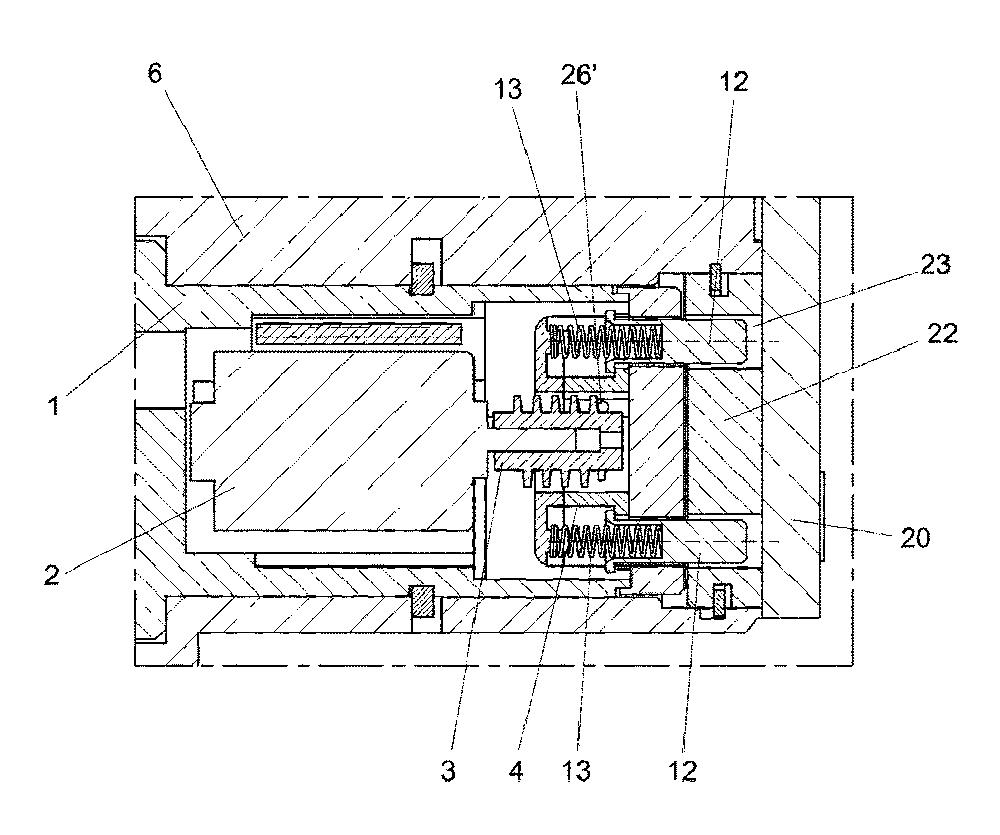
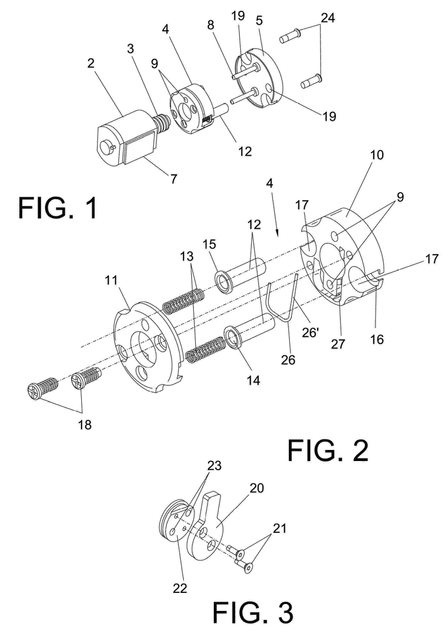
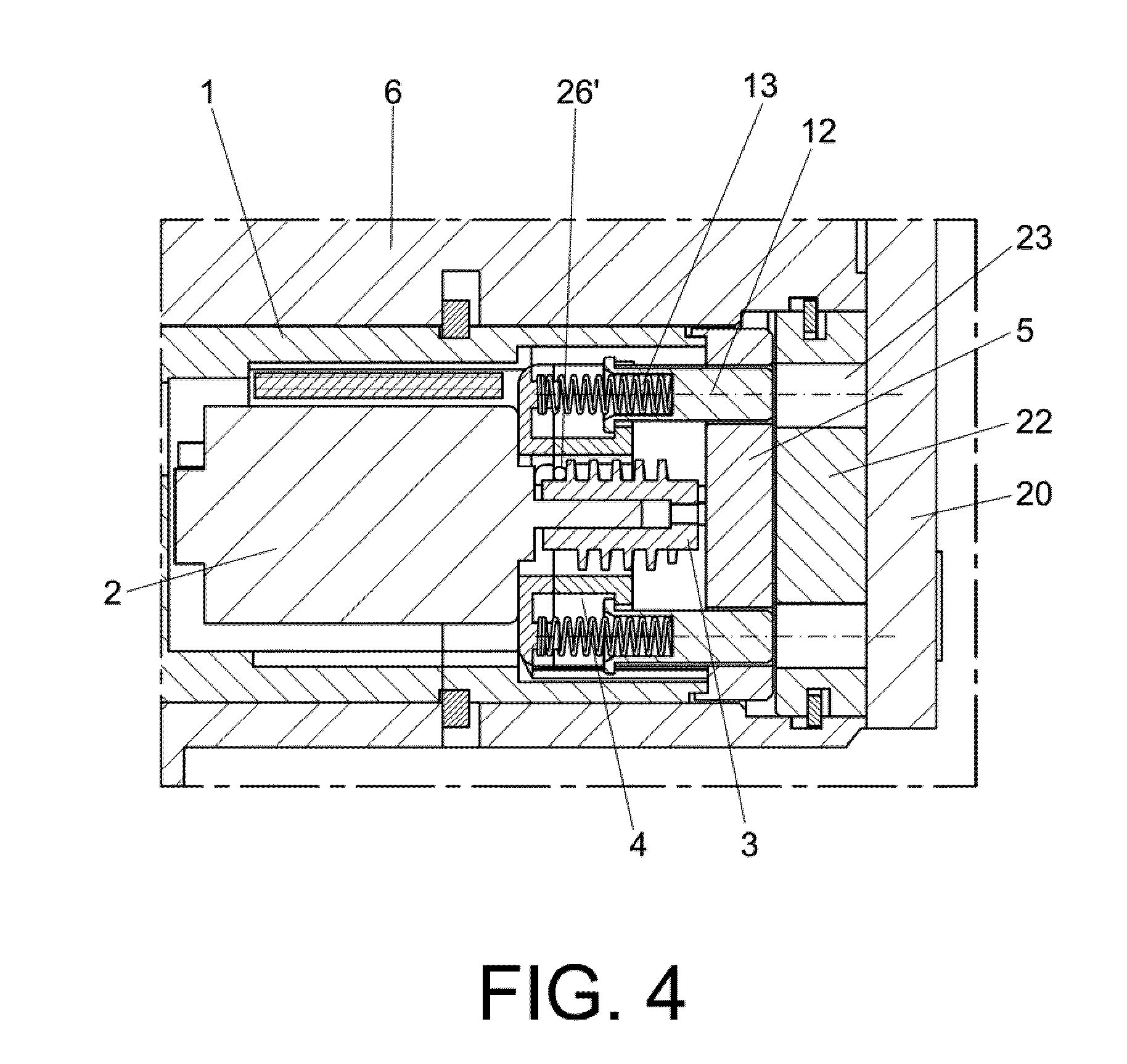
[0007]The mechanism of the invention presents certain particular characteristics on the basis of which the friction between the means that are moving or displaceable between themselves are minimum, therefore offering a minimum resistance, due to which it is possible to use motors of small dimensions since low power is required for the actuation.

[0008]Moreover, the elements corresponding to the actual clutch mechanism, according to the invention, are located in the same vertical plane, so that their lengths do not have to be summed up and therefore reducing the volume or space occupied by the actual clutch mechanism.

[0009]The fact can also be highlighted that, on the basis of the characteristics of the actual mechanism that are going to be explained below, it is possible to eliminate the end of travel detectors which physically also occupy a notable amount of space.

[0010]Specifically, the clutch mechanism of the invention is created on the basis of a carriage displaceable by means of...


PUM


Abstract

It comprises a carriage (4) displaceable forwards and backwards by means of a spindle (3) actuated by a motor (2), the carriage (4) containing clutch pins (12) so that in the forward displacement the engagement takes place with a clutch disc (22) integral with which is an eccentric, whose rotation will cause the actuation of the lock in which the unit is fitted. In its displacements the carriage (4) is guided in rods (8) provided in the corresponding cover (5) of a rotor (1) in which the motor (2) and carriage (4) assembly is housed. The clutch pins (12) are connected to pushing springs (13) for pushing them towards the emergency position and therefore that of engagement when those pins (12) are facing the holes (23) of the disc (22).

Description

OBJECT OF THE INVENTION[0001]As stated in the title of this descriptive specification, the present invention relates to a clutch mechanism applicable to electromechanical cylinders for locks, of the kind created on the basis of a cylinder that is fitted in the corresponding lock and incorporates in its interior a rotor containing the appropriate clutch means, on the basis of which it is able to interlock itself with a clutch disc integral with an eccentric which, as it rotates, is what produces the actuation of the lock.[0002]The aim of the invention is to achieve a clutch mechanism of small dimensions and with a minimum friction in the displaceable elements involved, and which consequently require a minimum effort for its actuation.BACKGROUND OF THE INVENTION[0003]Electromechanical locks are known whose functioning is based on introducing a code into the lock by means of a card or electronic key, which activates a mechanical system that carries out the locking or unlocking of the d...

Claims


Application Information

Patent Timeline
Patent Type & Authority Patents(United States)
IPC IPC(8): E05B47/06
CPCE05B47/0642F16D11/14E05B2047/0031E05B47/068Y10T70/7062Y10T70/5805Y10T70/5677Y10T70/5416Y10T70/5827Y10T70/7102Y10T70/7706Y10T70/5496E05B47/0676
Inventor IMEDIO OCANA, JUAN
Owner SALTO SYST SL
Why Eureka
Try Eureka