
Station

a technology for controlling stations and congestion, applied in data switching networks, frequency-division multiplexes, instruments, etc., can solve problems such as the inability of the protocol to prevent or eliminate the appearance of congestion autonomously, the risk of processing being interrupted or terminated in smsc b>3/b> or ppg, etc., to achieve the elimination of congestion in the interconnected station on the output side, the effect of reducing the degree of retention on the output sid

Inactive Publication Date: 2011-06-28
VODAFONE GRP PLC
View PDF11 Cites 0 Cited by
  • Summary
  • Abstract
  • Description
  • Claims
  • Application Information

AI Technical Summary

Benefits of technology

"The present invention provides a station for receiving and transmitting messages between interconnected stations. The station has congestion control means for detecting congestion in the output station and responding by delaying the acknowledgement of the message. The delay time can be set based on the average response time from the output station and a margin ratio. The congestion control means can also switch the message information to another session if there is congestion in the output station. The invention helps to prevent congestion and improve the overall efficiency of message transmission."

Problems solved by technology

In the PPG 2, the communication with the SMSC 3 is conducted with the communication protocol called SMPP (Short Message Peer-to-Peer), but flow control in the SMPP is not clearly defined and this protocol is considered to be unable to prevent or eliminate the appearance of congestion autonomously as a processing system.
The resultant problem is that there is a risk of processing being interrupted or terminated in the SMSC 3 or PPG 2 when congestion has occurred in the SMSC 3 or PPG 2.
Flow control support was also considered, but in order to produce the SMSC or PPG supporting the flow control, all the existing devices of those types had to be replaced which was unrealistic from the standpoint of cost.

Method used


Image

  • Station
  • Station
  • Station

Examples


Embodiment Construction

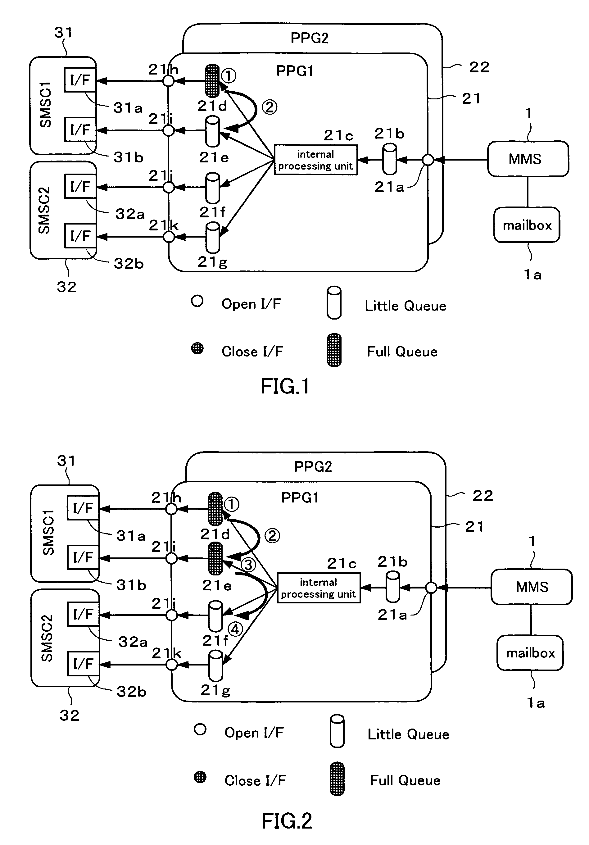
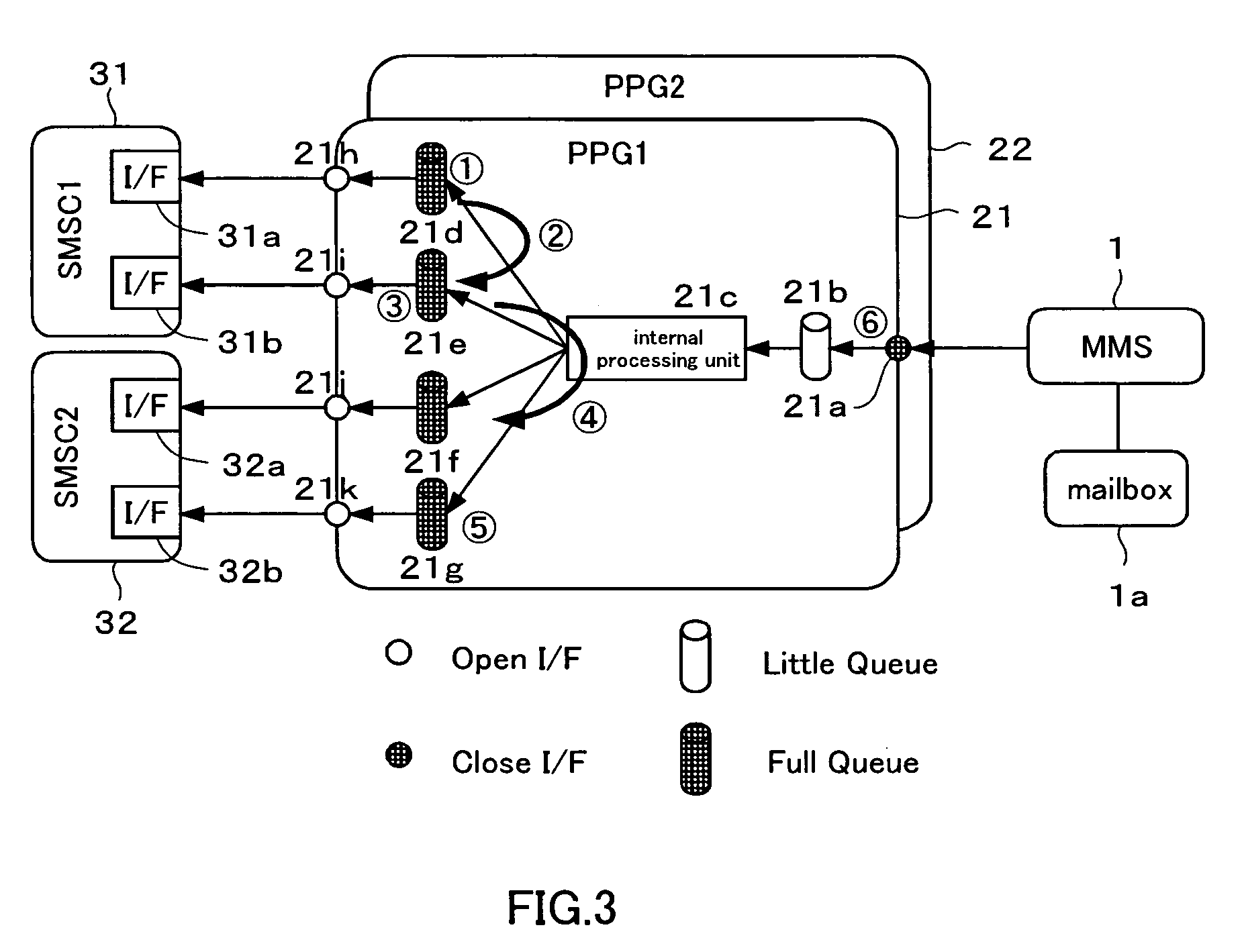
[0035]The configuration of the station of the preferred embodiment of the present invention is shown schematically in FIGS. 1 to 3. FIG. 1 shows a state in which congestion has occurred in a specific session. FIG. 2 shows a state in which congestion has occurred in a specific SMSC. FIG. 3 shows a state in which congestion has occurred in all the SMSC.

[0036]FIG. 1 shows only the configuration of the MMS 1, PPG 2, and SMSC 3 in the multimedia message allocation system shown in FIG. 5. The PPG 2 is composed of 2 units: a first PPG (PPG1) 21 and a second PPG (PPG2), and the SMSC 3 is also composed of two units: a first SMSC (SMSC1) 31 and a second SMSC (SMSC2) 32.

[0037]The congestion control means of the station in accordance with the present invention will be explained hereinbelow with reference to FIG. 1. If the MMS 1 receives a multimedia message (MM-message), the MM-message is stored in a mailbox 1a of the subscriber, which is a customer in the mailbox 1a, a reception notification t...


PUM


Abstract

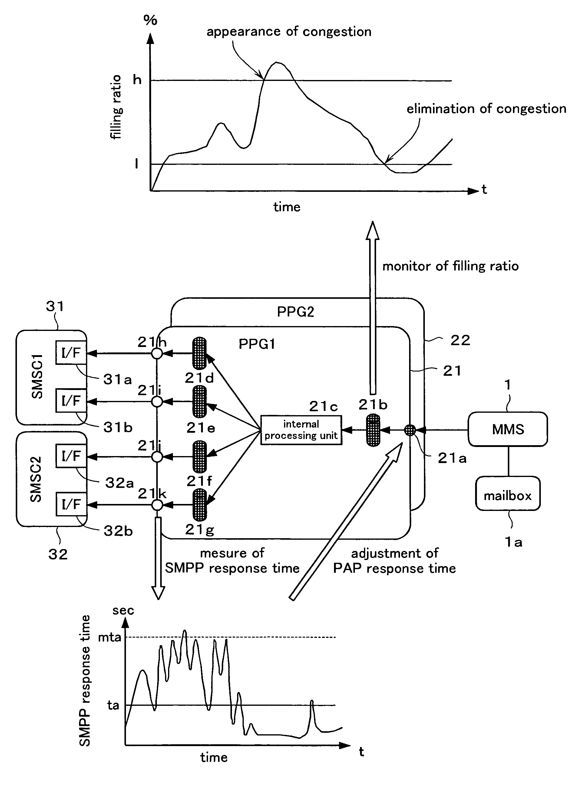
With the object of eliminating congestion that has occurred in a station which can not prevent or eliminate the occurrence of congestion autonomously, the SMPP response time in output interfaces 21h-21k of a first PPG 21 are measured and when the time mta, which is m-times of the SMPP response time ta in the normal state, is exceeded, congestion is assumed to occur in an interconnected station of the first PPG 21 and the response to push transfer request in an input interface 21a is delayed. Further, changes in the filling ratio in a buffer memory 21b are monitored and when the filling ratio exceeds h %, a decision is made that congestion has occurred in the first PPG 21 and the response to the push transfer request in the input interface 21a is delayed.

Description

[0001]This application is the U.S. National Phase under 35 U.S.C. §371 of International Application PCT / JP2004 / 002756, filed on Mar. 4, 2004, which claims priority of Japanese Patent Application No. 2003-071391, which was filed on Mar. 17, 2003. The International Application was published under PCT Article 21(2) in a language other than English.TECHNICAL FIELD[0002]The present invention relates to congestion control of a station for receiving a message from an interconnected station on the input side and transmitting the message information relating to the received message to the interconnected station on the output side.BACKGROUND ART[0003]Recently developed cellular telephone systems can receive and transmit multimedia messages including static images, dynamic images, and music. Such multimedia messages can be transmitted and received via internet by cellular telephones adapted to multimedia messages and can be exchanged between the cellular telephones adapted to multimedia messag...

Claims


Application Information

Patent Timeline
Patent Type & Authority Patents(United States)
IPC IPC(8): H04J3/14H04L1/00H04L12/26H04L12/28H04L12/16H04W24/00H04L47/30H04M3/00H04W4/12H04W28/14H04W88/18
CPCH04L47/10H04L47/32H04W88/184H04W28/14H04W4/12
Inventor YOSHIMURA, TAKASHITODE, TOSHIHISATAMAKI, SYOZO
Owner VODAFONE GRP PLC
Learn More