Signal conversion apparatus and signal conversion method

a signal conversion and signal technology, applied in the direction of digital transmission, pulse automatic control, super-regenerative demodulator circuit, etc., can solve the problems of degraded receiving performance, high cost of oscillator employing this configuration to prevent frequency pulling, and degraded functional performance of the frequency conversion apparatus, so as to prevent performance degradation, prevent performance degradation, and manufacture by a simple process

Inactive Publication Date: 2011-06-28
FURUNO ELECTRIC CO LTD
View PDF6 Cites 0 Cited by
  • Summary
  • Abstract
  • Description
  • Claims
  • Application Information

AI Technical Summary

Benefits of technology

[0020]The present invention is intended to solve the aforementioned problems of the prior art. Accordingly, it is an object of the invention to provide a compact, low-cost signal conversion apparatus which can be manufactured by a simple process, yet featuring a capability to prevent performance degradation due to frequency pulling and output a signal having a desired property. It is another object of the invention to provide a signal conversion method which makes it possible to prevent performance degradation due to frequency pulling and output a signal having a desired property.
[0021]According to the invention, a signal conversion apparatus includes a local oscillator for locally generating a signal having a specific frequency, a phase shifter for shifting the phase of the locally generated signal output from the local oscillator by an amount determined based on a relationship between the amount of phase shift and the amount of frequency pulling, and a converter for converting an input signal by using the phase-shifted locally generated signal output from the phase shifter. The signal conversion apparatus thus configured makes it possible to positively create a load curve which prevents variations in the oscillating frequency of the locally generated signal. This configuration serves to provide a compact, low-cost signal conversion apparatus capable of preventing the occurrence of the frequency pulling phenomenon by a simple adjustment procedure.
[0033]In yet another aspect of the invention, the aforementioned phase shifter is configured by using a transmission line, a lumped constant circuit or a distributed constant circuit, whereby the signal conversion apparatus can be constructed with a compact, low-cost circuit configuration.
[0034]According to the present invention, the signal conversion apparatus is provided with the phase shifter for varying the impedance existing between the local oscillator and the converter by positively creating a load curve which prevents variations in the oscillating frequency of the locally generated signal output from the local oscillator. This circuit configuration makes it possible to prevent the occurrence of the frequency pulling phenomenon even when power of the input signal fed into the converter increases. As the phase shifter serves to avert the occurrence of the frequency pulling phenomenon, the circuit configuration of the invention makes it possible to manufacture a compact, low-cost signal conversion apparatus capable of outputting a signal having a desired property by a simple adjustment procedure without necessarily requiring an active circuit.
[0035]The circuit configuration of the present invention is particularly advantageous when applied to a frequency conversion device used in a magnetron radar, for example. Even when implemented to handle a signal generated by a magnetron whose oscillating frequency is unstable and signal intensity varies at short intervals, the circuit configuration of the invention serves to prevent frequency pulling and improve reliability of data contained in transmit / receive signals.

Problems solved by technology

As the frequency f3 of the signal generated by the local oscillator 101 varies in this fashion, the frequency f2 of each output signal of the mixer 102 varies and this causes degradation in functional performance of the frequency conversion apparatus.
This poses a problem that a narrow-band receiver used for receiving the radio wave transmitted by using the modulating apparatus of FIG. 12 can only achieve degraded receiving performance.
The oscillator employing this configuration to prevent frequency pulling is however expensive compared to ordinary oscillators without such a configuration.
This develops such problems as greater complexity of circuit configuration of the local oscillator 101 and an increase in circuit scale.
The second approach has another problem that it is sometimes impossible to completely prevent the occurrence of the frequency pulling phenomenon in actuality.

Method used


Image

  • Signal conversion apparatus and signal conversion method
  • Signal conversion apparatus and signal conversion method
  • Signal conversion apparatus and signal conversion method

Examples


first embodiment

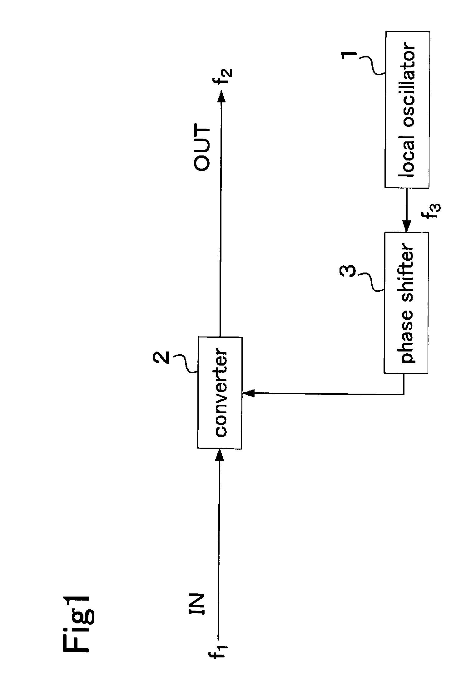
[0052]FIG. 1 is a block diagram showing the configuration of a signal conversion apparatus according to a first embodiment of the invention for converting an incoming signal by using a locally generated signal output from a local oscillator 1 while preventing the occurrence of the frequency pulling phenomenon by adjusting the amount of phase shift of the locally generated signal by means of a phase shifter 3 connected between the local oscillator 1 and a converter 2. The first embodiment of the invention is described more specifically with reference to a frequency conversion apparatus which is one example of the signal conversion apparatus.

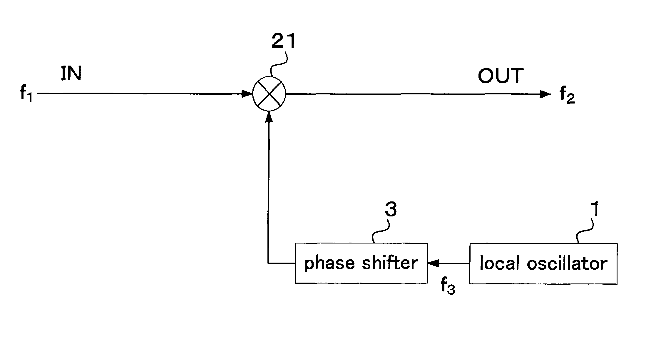
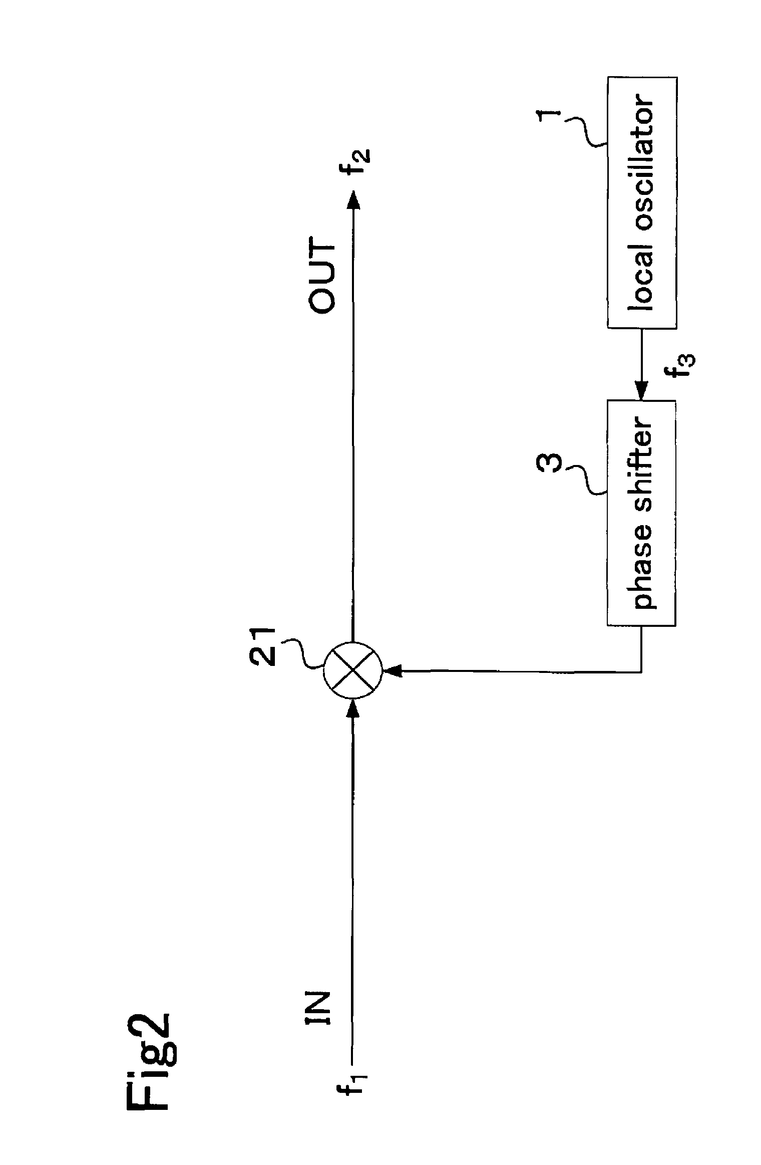
[0053]FIG. 2 is a block diagram showing the configuration of a frequency conversion apparatus according to the first embodiment of the invention. As shown in FIG. 2, the frequency conversion apparatus includes a local oscillator 1, a mixer 21 and a phase shifter 3.

[0054]The local oscillator 1 generates and outputs a signal (locally generated signa...

second embodiment

[0086]While the invention has been described with reference to the frequency conversion apparatus taken as a typical example of the signal conversion apparatus in the first embodiment, the above-described approach of the first embodiment to preventing the frequency pulling phenomenon by the phase shifter 3 is applicable not only to the frequency conversion apparatus but similarly to every kind of signal conversion apparatus which is configured to convert an incoming signal by using a signal output from a local oscillator.

[0087]FIG. 8 is a block diagram showing the configuration of a modulating apparatus according to a second embodiment of the invention which is provided with a local oscillator 1, a modulator 22 and a phase shifter 3. In the modulating apparatus of FIG. 8, an input signal (modulating signal) is a rectangular pulse wave having a frequency f1 and a signal (carrier signal) output from the local oscillator 1 is a sine wave having a single frequency f3.

[0088]In this modul...


PUM


Abstract

A signal conversion apparatus includes a local oscillator for locally generating a signal having a frequency, a phase shifter for shifting the phase of the locally generated signal output from the local oscillator by an amount determined based on a relationship between the amount of phase shift and the amount of frequency pulling, and a converter for converting an input signal by using the phase-shifted locally generated signal output from the phase shifter. The phase shifter varies impedance between the local oscillator and the converter so that the oscillating frequency of the locally generated signal output from the local oscillator remains unchanged.

Description

CROSS REFERENCE OF RELATED APPLICATION[0001]Japanese Patent Application Tokugan No. 2005-202473 is hereby incorporated by reference.BACKGROUND OF THE INVENTION[0002]1. Field of the Invention[0003]The present invention relates to a signal conversion apparatus for converting an incoming signal by using a signal fed from a local oscillator. More particularly, the invention pertains to a technique for reducing an adverse influence of load variations on a local oscillator.[0004]2. Description of the Related Art[0005]FIG. 9 is a block diagram showing a basic configuration of a conventional frequency conversion apparatus provided with a local oscillator. The frequency conversion apparatus includes a mixer 102 which mixes an input signal having a frequency f1 and a signal having a specific frequency f3 output from a local oscillator 101 to produce two output signals having desired frequencies f2 equal to the sum and difference of the two input frequencies f1, f3 expressed by (f1+f3) and |f1...

Claims


Application Information

Patent Timeline
Patent Type & Authority Patents(United States)
IPC IPC(8): H04B1/00
CPCH03D11/00H04L25/0278H04B1/28H03C3/10H03L7/06H04L27/0014
Inventor HIROSE, TAKAYOSHIKASHIWA, TAKUO
Owner FURUNO ELECTRIC CO LTD
Why Eureka
Try Eureka