
Eye wall anchored fixtures

a technology for anchored fixtures and eye walls, applied in the field of eye wall anchored fixtures, can solve problems such as eye infections, other undesirable complications, and their actual drug delivery rate being lower than their intended drug delivery rate, or even completely blocked to the detriment of the patien

Inactive Publication Date: 2011-07-12
FORSIGHT VISION5 INC
View PDF39 Cites 23 Cited by
  • Summary
  • Abstract
  • Description
  • Claims
  • Application Information

AI Technical Summary

Benefits of technology

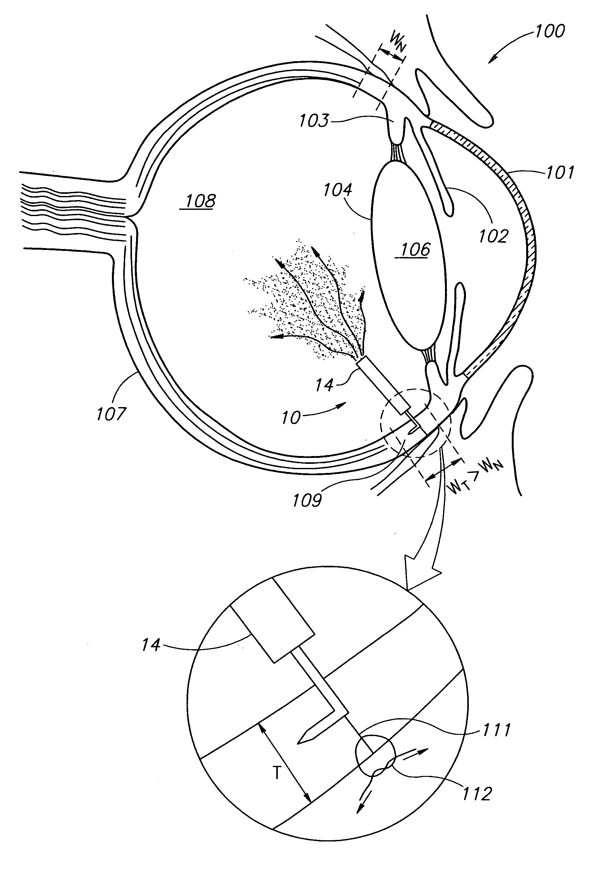
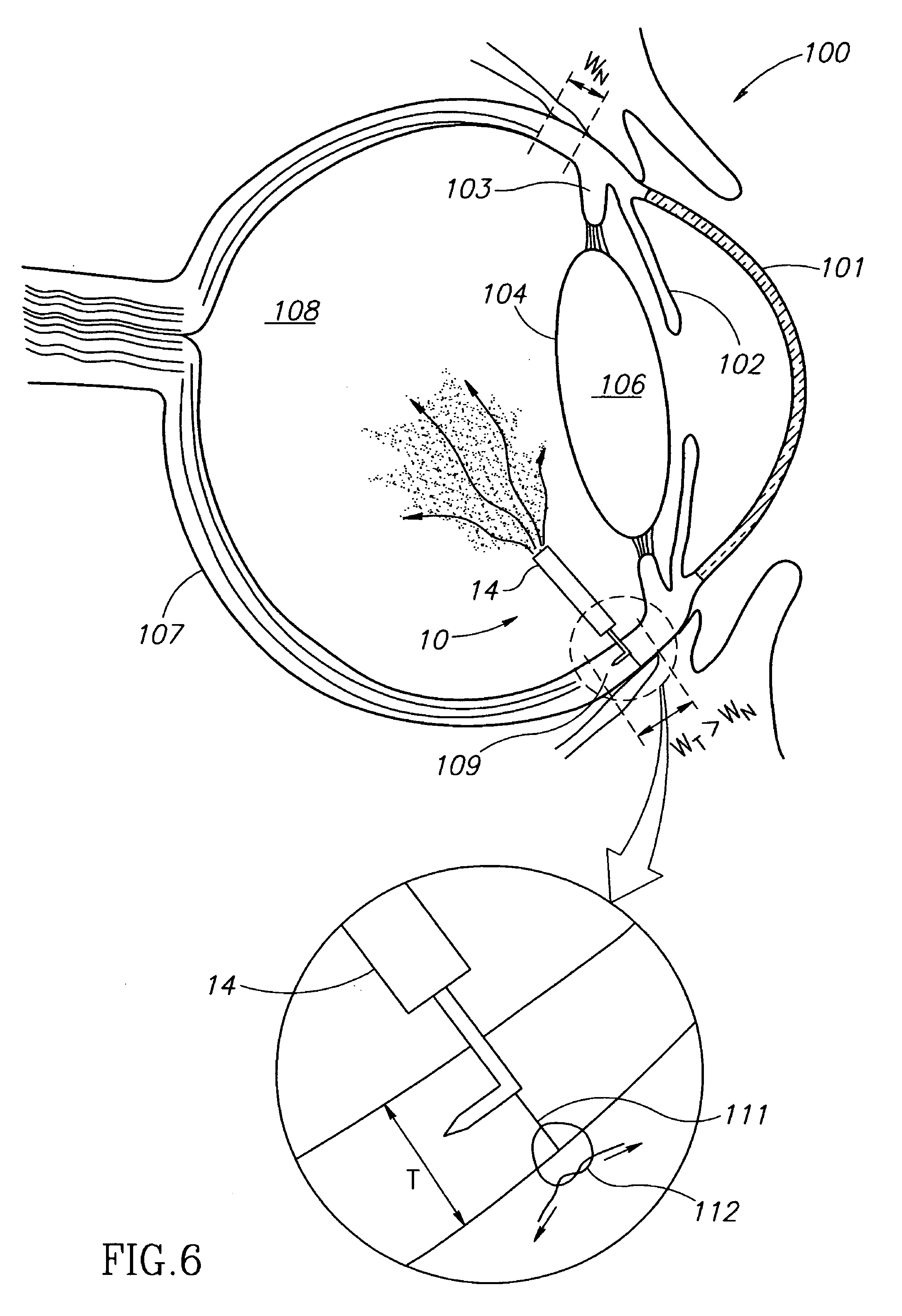
[0007]The present invention is for eye wall anchored fixtures having at least one elongated anchor member for driven lengthwise insertion into an eye wall for supporting an intraocular device in the eye's vitreous cavity. Fixtures are intended for implantation in a circumferential segment of an eye wall devoid of retinal tissue and blood vessels called the pars plana The width of an average human adult eye's pars plana increases from a minimum width WN of about 1 mm towards his nose to a maximum width WT of about 2 mm towards his temporal region. Fixtures are preferably anchored in circumferential incisions in a human adult eye's pars plana preferably 3.5 mm posterior to its corneal limbus, perpendicular to a circumferential incision, and in a transverse direction to the eye wall's thickness. Fixtures are preferably anchored temporally since an eye's pars plana is not only wider but also more accessible.

Problems solved by technology

Shots of specific drug quantities are administered at the present time by intraocular injection notwithstanding that they are traumatic and can lead to eye infections, and other undesirable complications.
However, the operation of such intraocular drug dispensers are often impeded by natural fibrous tissue growing thereon resulting in their actual drug delivery rate being lower than their intended drug delivery rate or even completely blocked to the detriment of an intended treatment.

Method used


Image

  • Eye wall anchored fixtures
  • Eye wall anchored fixtures
  • Eye wall anchored fixtures

Examples


Embodiment Construction

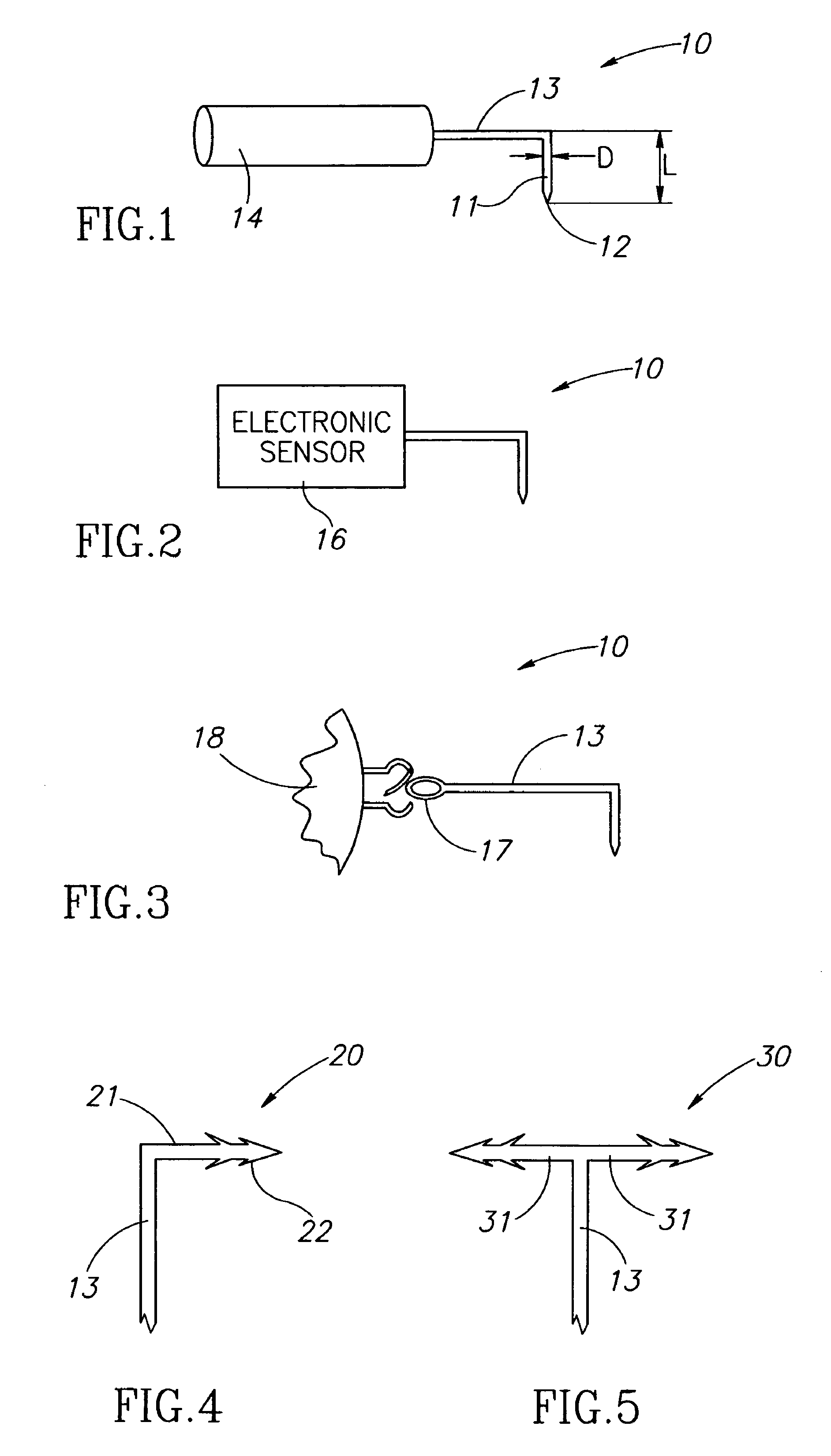
[0022]FIGS. 1-3 show eye wall anchored L-shaped fixtures 10 having a generally L-shaped structure including an elongated anchor member 11 with a pointed leading end 12, and a support member 13. The anchor members 11 have a length L in the range of about 1 mm to about 3 mm, and preferably 2 mm±0.5 mm, and a diameter D in the range of about 100 μm to about 200 μm, and preferably 150 μm±10 μm. The fixtures 10 are made from a biocompatible material suitable for implantation in an eye wall, and preferably stainless steel so as to be enable slight resilient deformation from their preferred right angle configuration for facilitating some flexibility to deploy an intraocular device in a preferred location in an eye's vitreous cavity. The support member 13 can be provided with a drug release capsule 14 for intraocular drug administration (see FIG. 1), an electronic sensor 16 for acquiring intraocular measurements for monitoring and / or diagnostic purposes (see FIG. 2), and the like. Alternati...


PUM


Abstract

Eye wall anchored fixtures each including at least one elongated anchor member for driven lengthwise insertion into an eye's eye wall in a transverse direction to its thickness for supporting an intraocular device in the eye's vitreous cavity. Fixtures are preferably anchored in circumferential incisions in a human adult eye's pars plana preferably 3.5 mm posterior to its corneal limbus, and perpendicular to a circumferential incision. The fixtures are either generally L-shaped with a single elongated anchor member designed for withdrawal from an eye wall or self-anchoring thereinto, or generally T-shaped with a pair of oppositely directed self-anchoring elongated anchor members for sealing a throughgoing incision. Intraocular devices can be designed for intraocular drug delivery, for acquiring intraocular physiological measurements, and the like.

Description

CROSS-REFERENCE TO RELATED APPLICATIONS[0001]This application is a United States Continuation-In-Part (CIP) application of PCT International Application PCT / IL2005 / 000003 having an international filing date of 3 Jan. 2005 and designating the United States, the contents of which are hereby incorporated by reference in their entirety.[0002]This application also claims the benefit of prior U.S. provisional patent application No. 60 / 759,060 filed 17 Jan. 2006, the contents of which are hereby incorporated by reference in their entirety.FIELD OF THE INVENTION[0003]The invention pertains to eye wall anchored fixtures.BACKGROUND OF THE INVENTION[0004]Certain eye conditions including inter alia Age related Macular Degeneration (AMD), diabetic macular edema, uveitis, and the like, require specific drug quantities at regular intervals for undetermined periods of time. Shots of specific drug quantities are administered at the present time by intraocular injection notwithstanding that they are ...

Claims


Application Information

Patent Timeline
Patent Type & Authority Patents(United States)
IPC IPC(8): A61M35/00A61F2/14A61F2/00A61K9/22A61M31/00
CPCA61B3/165A61B5/076A61B5/4839A61B5/6882A61B17/00234A61B17/0401A61F9/0017A61B2017/06176
Inventor NUN, JOSHUA BEN
Owner FORSIGHT VISION5 INC
Learn More