Bone plate
- Summary
- Abstract
- Description
- Claims
- Application Information
AI Technical Summary
Benefits of technology
Problems solved by technology
Method used
Image
Examples
Embodiment Construction
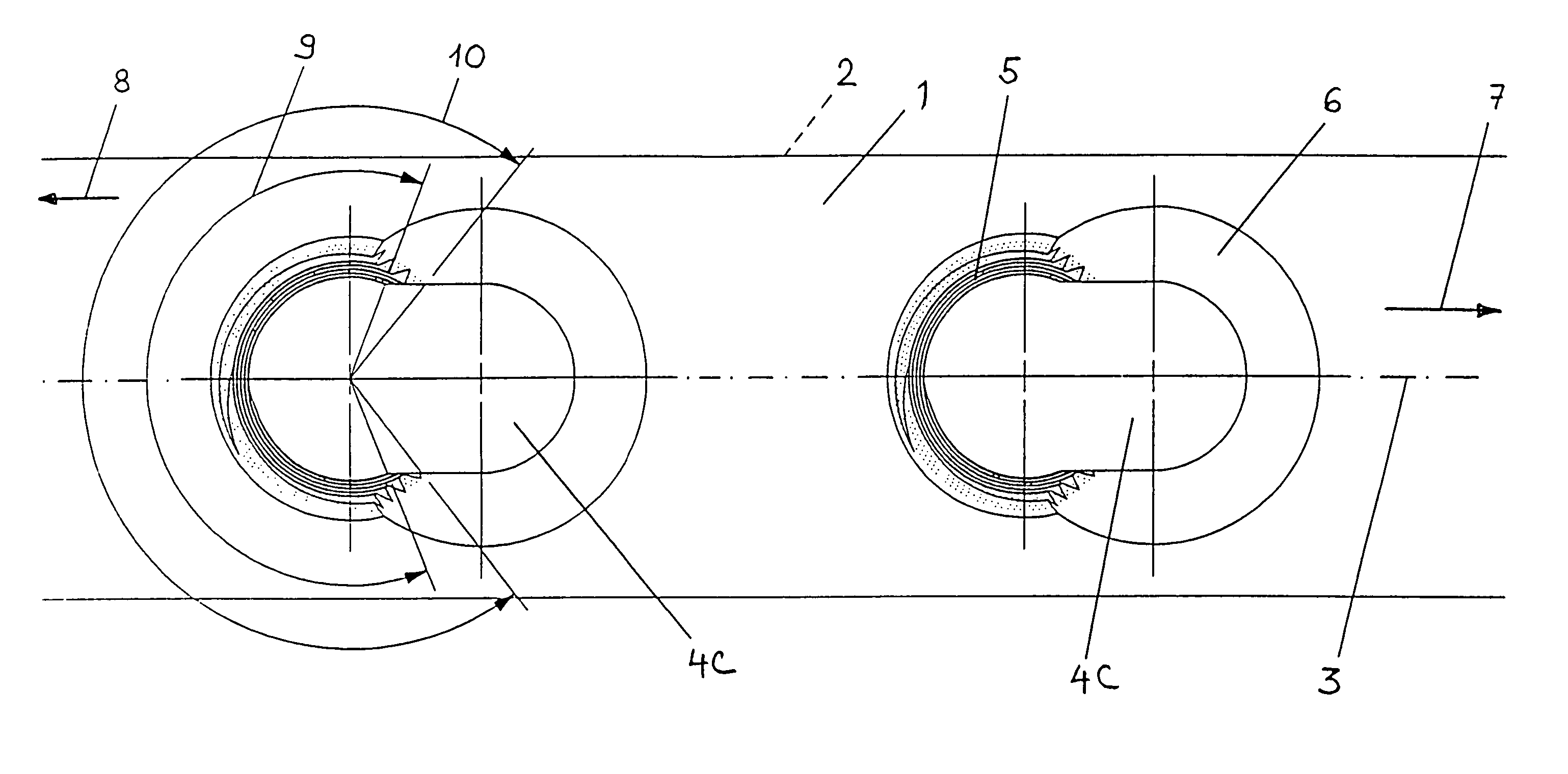
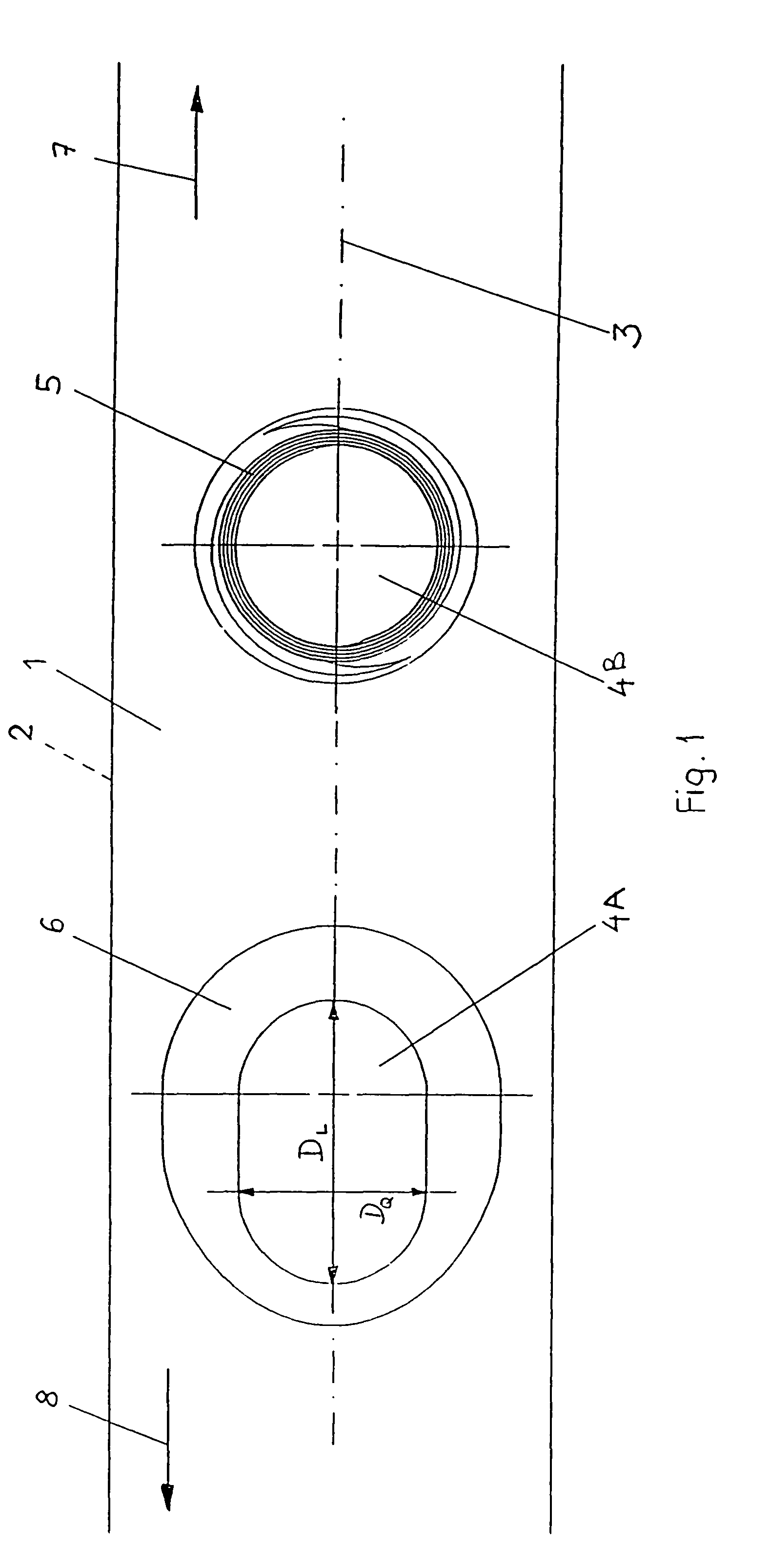
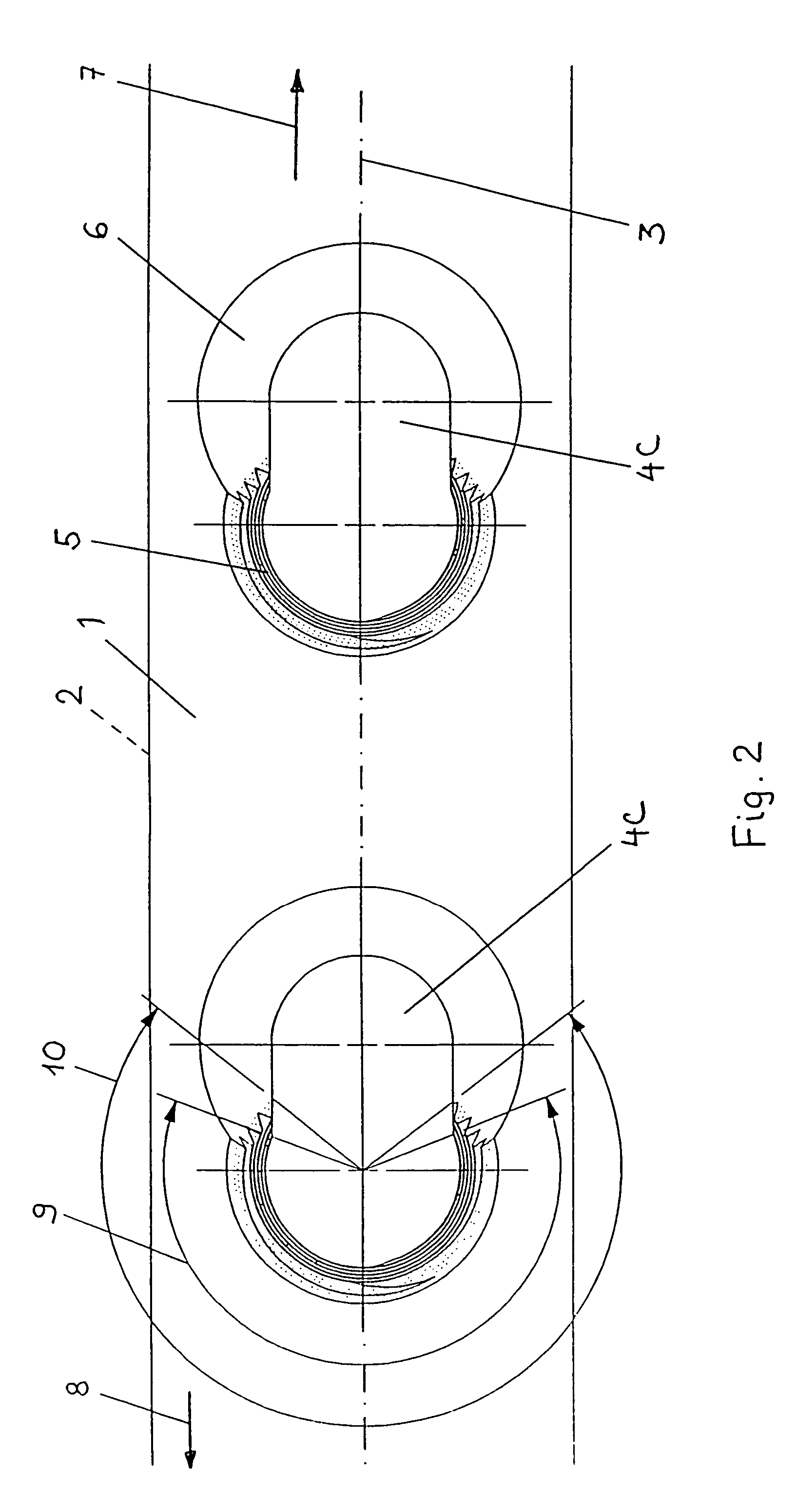
[0025]One embodiment of a bone plate according to the present invention is shown in FIG. 1. The bone plate includes an upper surface 1, a bone-contacting surface 2, and defines a longitudinal axis 3. The bone plate further includes two holes 4A and 4B, which are generally located along the longitudinal axis 3, and extend through the bone plate from upper surface 1 to bone-contacting surface 2. Holes 4A and 4B are dimensioned and configured to receive the heads of bone screws. As shown in FIG. 1, arrow 7 indicates a longitudinal direction toward one end of the bone plate and arrow 8 indicates a longitudinal direction toward a central portion of the bone plate.
[0026]Still referring to FIG. 1, hole 4A, which is located closer to the central portion of the bone plate, is elongated along the longitudinal axis 3 of the bone plate. More specifically, hole 4A defines first and second dimensions on bone-contacting surface 2. First dimension DL is substantially parallel to longitudinal axis 3...
PUM
 Abstract
Description
Claims
Application Information
 - R&D
- Intellectual Property
- Life Sciences
- Materials
- Tech Scout
- Unparalleled Data Quality
- Higher Quality Content
- 60% Fewer Hallucinations
Browse by: Latest US Patents, China's latest patents, Technical Efficacy Thesaurus, Application Domain, Technology Topic, Popular Technical Reports.
© 2025 PatSnap. All rights reserved.Legal|Privacy policy|Modern Slavery Act Transparency Statement|Sitemap|About US| Contact US: help@patsnap.com


