Control element with proximity sensor

a technology of proximity sensor and control element, which is applied in the direction of electrical equipment, electronic switching, pulse technique, etc., can solve the problems of the element cannot be identified by the user, and achieve the effect of small space required by the control element, affecting the visual appearance of the control element, and easy forwarded

Inactive Publication Date: 2011-07-12
CONTINENTAL AUTOMOTIVE GMBH
View PDF16 Cites 31 Cited by
  • Summary
  • Abstract
  • Description
  • Claims
  • Application Information

AI Technical Summary

Benefits of technology

[0004]According to a preferred embodiment of the present invention, the control element includes a switching element, an operating element for operating the switching element, a printed circuit board, and an electrically conductive sensor element of a capacitive proximity sensor integrated in the operating element. The electrically conductive sensor element is designed to be electrically conductively connected to the printed circuit board. The sensor element being integrated in the operating element means that the sensor element either forms part of the operating element or is arranged inside the operating element. In any case, however, the sensor element cannot be identified by the user and therefore in no way adversely affects the visual appearance of the control element. The corresponding electrically conductive connection of the sensor element to the printed circuit board allows a sensor signal from the sensor element to be forwarded easily to signal-processing elements, which can be arranged on the printed circuit board. A suitable arrangement of the sensor element as a part of or within the operating element and a suitable connection of the sensor element to the printed circuit board ensure that the conventional functionality of the control element, which can particularly be formed as a pushbutton switch, is not adversely affected.
[0005]The sensor element may be formed as an angled, elastically deformable metal element or metal-coated plastic element which has a first and a second leg, wherein the first leg projects into the operating element and is fixedly connected thereto, and the second leg is supported on a conductive face of the printed circuit board on a side of the printed circuit board which faces the operating element. This ensures that the sensor element is securely connected to the printed circuit board. Even when the operating element is operated, particularly when an operating element of a pushbutton switch is pressed, the elastically deformable configuration of the metal element or of the metal-coated plastic element ensures reliable contact with the printed circuit board in all phases of the operation of the control element.
[0006]The sensor element may be formed as an angled, elastically deformable metal element which has a first leg and a second leg, wherein the first leg is fixedly connected to the printed circuit board and the second leg acts on an inner front portion of the operating element as a spring element. In this arrangement, the sensor element simultaneously brings about the returning of the operating element of the pushbutton switch into the position of rest, so that this requires no additional elements such as a spring or an elastic rubber element. The space required by a control element, which is small anyway, can be even lowered as a result of this combination of sensor element and returning element.
[0007]The sensor element may have a portion which is provided with a metal coating, projects through the printed circuit board and, in a position in which the pushbutton switch is at rest, rests against a conductive face of a side of the printed circuit board which is remote from the operating element. The sensor element and possibly also an additional element for field orientation are in this case implemented by means of a two-component operating element with a partly metal coating. In this case, the electrical connection of the sensor element to the printed circuit board is likewise made via the metal-coated region of the operating element. The operating element and the sensor element are therefore of integral design, so that additional assembly complexity is not required.
[0010]In another embodiment, the switching element may contain a switching mat arranged on the printed circuit board, the sensor element may have been arranged on the operating element as a metal coating, and the switching mat may have an electrically conductive layer which is connected both to the conductive coating of the operating element and to the printed circuit board. The use of an electrically conductive plastic material for subregions of the operating element and of a conductive coating, connected thereto, for a switching mat in the form of a switching element provides a simple way of establishing a conductive connection between the sensor element and the printed circuit board. In particular, this embodiment allows the operating element to engage on the side of the switching mat opposite to the operating element, with the conductive coating of the operating element, in a position in which the control element is at rest, resting against the electrically conductive layer of the switching mat. In this case, the switching mat is simultaneously used as a stop for the operating element in the position of rest, its rubber-like material simultaneously ensuring noise damping when the key is returned from the operating position to the position of rest.

Problems solved by technology

In any case, however, the sensor element cannot be identified by the user and therefore in no way adversely affects the visual appearance of the control element.

Method used


Image

  • Control element with proximity sensor
  • Control element with proximity sensor
  • Control element with proximity sensor

Examples


Embodiment Construction

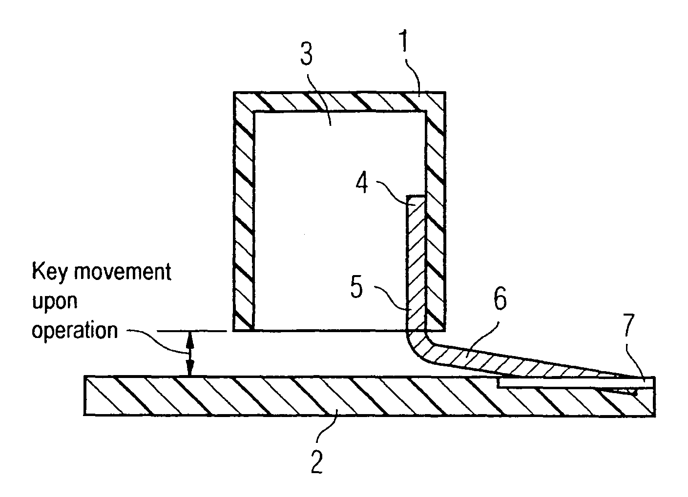
[0020]FIG. 1 schematically shows a control element formed as a pushbutton switch with a linearly moving operating element 1 which is mounted in conventional fashion in a support element (not shown here) so as to move linearly. Pressure on the operating element 1 moves it toward the printed circuit board 2. The operating element 1 may be returned to the position of rest by a spring element (likewise not shown), for example. The operating element 1 has an interior space 3. Projecting into the interior space 3 of the operating element 1 is a first leg 4 of an angled and elastically deformable metal element 5. The first leg 4 is firmly connected to the operating element 1, which is made of a plastic material. A second leg 6 is arranged at an angle of slightly more than 90 degrees relative to the first leg 4 and is supported on a conductive face 7 of the printed circuit board 2. The second leg 6 is electrically connected to the printed circuit board 2 by means of snap-in hooks.

[0021]When...


PUM


Abstract

A control element includes a switching element, an operating element for operating the switching element, a printed circuit board, and an electrically conductive sensor element of a capacitive proximity sensor integrated in the operating element. The electrically conductive sensor element is designed to be electrically conductively connected to the printed circuit board.

Description

BACKGROUND OF THE INVENTION[0001]The invention relates to a control element, particularly for a motor vehicle component, having an operating element which is mounted so as to move in a support element and which acts on a switching element, in particular.[0002]To control motor vehicle components, such as in a radio appliance, in a navigation appliance, in a car telephone, in a multimedia installation and the like, control and display devices are frequently used which are arranged ergonomically in the vehicle. In this case, the display device should be arranged such that the driver can observe it with as little diversion from the road traffic as possible. The display unit is therefore preferably arranged in the region of the dashboard or in the upper region of a central console. The control unit is preferably arranged such that the driver can reach it with his fingers without a relatively great arm movement. However, this arrangement of the control unit has the drawback that the contr...

Claims


Application Information

Patent Timeline
Patent Type & Authority Patents(United States)
IPC IPC(8): H03K17/975
CPCB60K37/06H03K17/975H03K2217/9653
Inventor BORN, FRANKMANKEL, NORBERTREINHARDT, JOERGSCHAEFER, STEFANWUSTENBECKER, DIRK
Owner CONTINENTAL AUTOMOTIVE GMBH
Why Eureka
Try Eureka