Automatic exhaust fan control apparatus and method

a technology of automatic exhaust fan and control apparatus, which is applied in the field of ventilation systems, can solve the problems of uncontrolled humidity, mold and mildew growth, deterioration of the environment, etc., and achieve the effect of simple installation and use, and economic manufactur

Inactive Publication Date: 2011-07-26
KARO USA SYST
View PDF6 Cites 5 Cited by
  • Summary
  • Abstract
  • Description
  • Claims
  • Application Information

AI Technical Summary

Benefits of technology

[0011]Yet another object of the present invention is to provide humidity and odor control apparatus that provides for automatic shut-off of the air moving device after a preset period of time.
[0013]Yet a further object of the present invention is to provide a humidity and odor control apparatus that prevents undue tampering by children.
[0014]An additional object of the present invention is to provide a humidity and odor control apparatus that draws low levels of electrical power during operation.
[0016]Yet another object of the present invention is to provide a humidity and odor control apparatus that is economical to manufacture.
[0017]A further object of the present invention is to provide a humidity and odor control apparatus that is simple to install and use.

Problems solved by technology

As is generally well known uncontrolled humidity in rooms, bathrooms, basements and the like confines leads to their deteriorating conditions.
Effects of uncontrolled humidity are particularly felt in the bathrooms where the moist air condenses on the various surfaces generally leading to mold and mildew growth.
However, it has been found that often the fan is either not operating for a sufficient period of time either due to the user forgetting to actuate the switch or prematurely deactivating it or is left running for a longer than required period of time, if the user forgets to turn it off, thus wasting electric energy.
However, it has been found that often odor remains in the bathroom after the exhaust fan has been turned off.

Method used


Image

  • Automatic exhaust fan control apparatus and method
  • Automatic exhaust fan control apparatus and method
  • Automatic exhaust fan control apparatus and method

Examples


Embodiment Construction

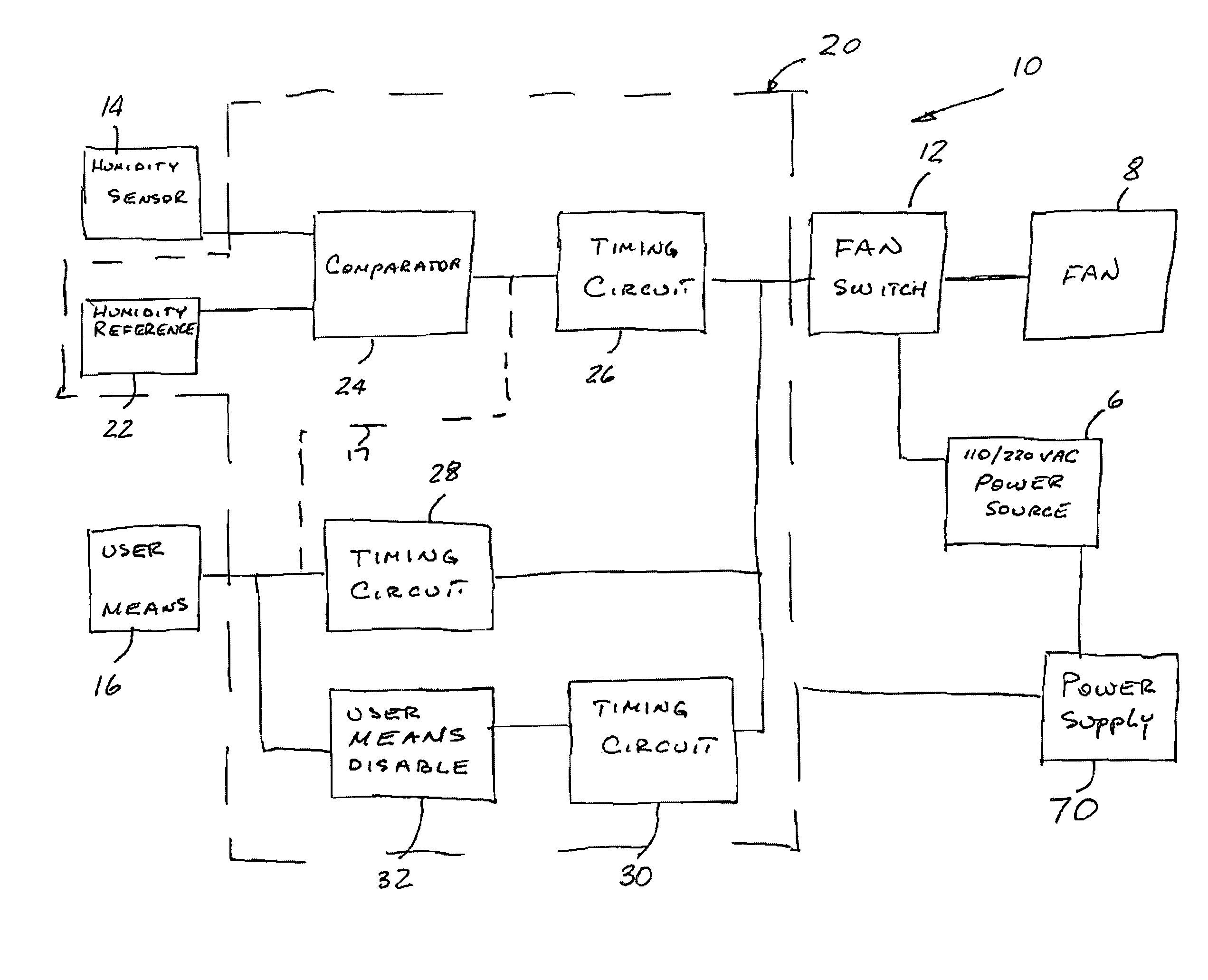
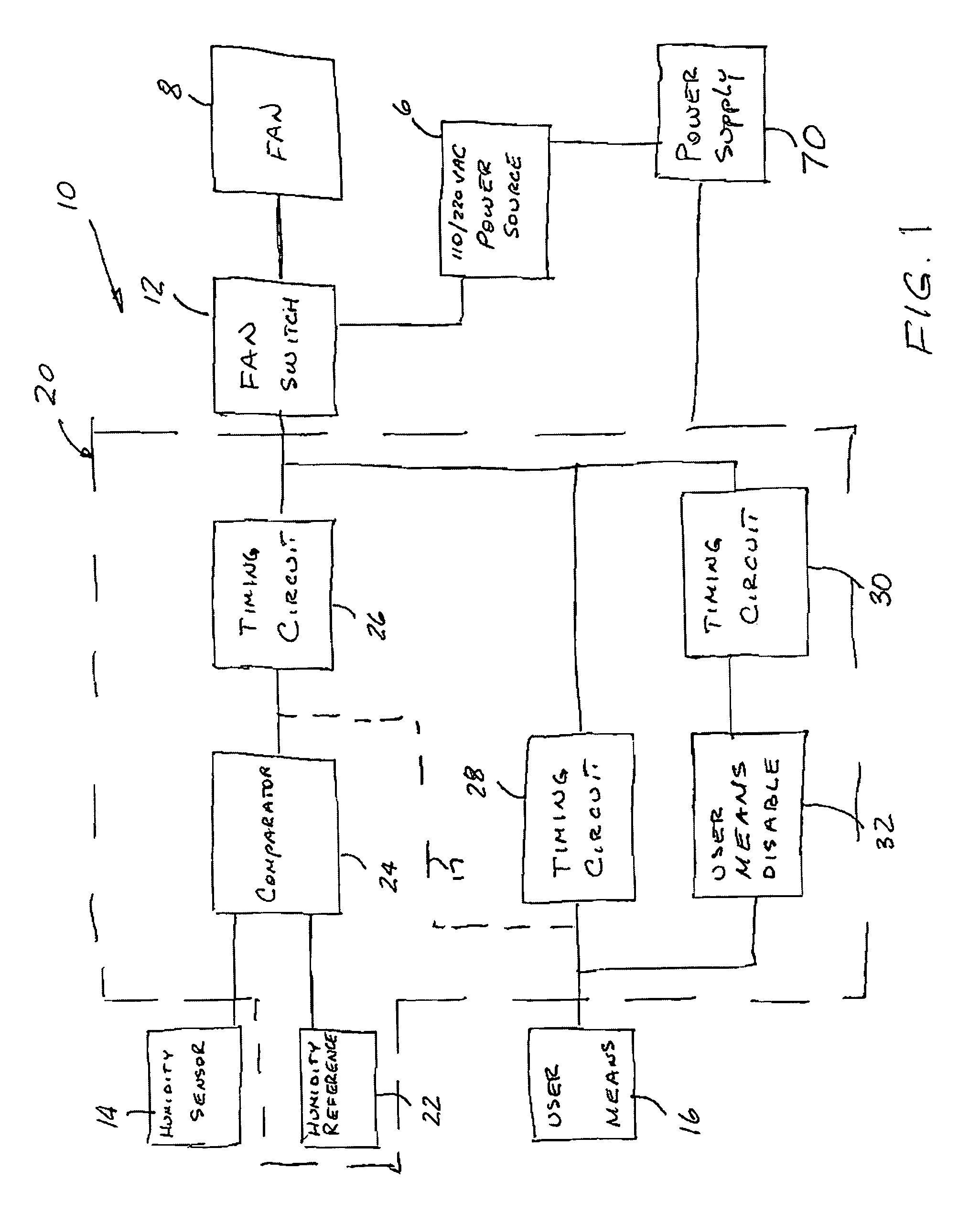
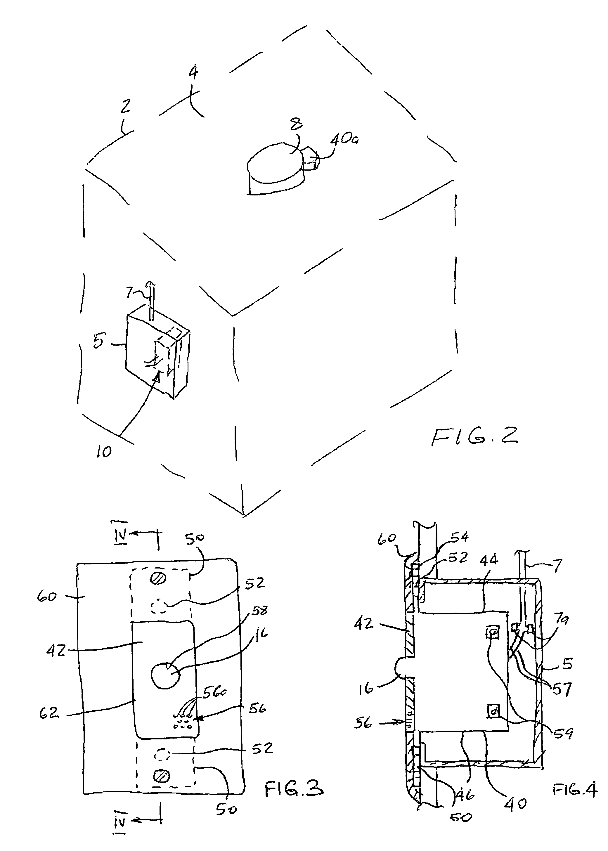
[0023]Prior to proceeding to the more detailed description of the present invention, it should be noted that, for the sake of clarity and understanding, identical components which have identical functions have been identified with identical reference numerals throughout the several views illustrated in the drawing figures.

[0024]The best mode for carrying out the invention is presented in terms of its presently preferred embodiment, herein depicted within FIGS. 1 through 4. However, the invention is not limited to the described embodiment, and a person skilled in the art will appreciate that many other embodiments of the invention are possible without deviating from the basic concept of the invention and that any such work around will also fall under scope of this invention. It is envisioned that other styles and configurations of the present invention can be easily incorporated into the teachings of the present invention, and only one particular configuration shall be shown and desc...


PUM


Abstract

A control apparatus for operating an exhaust fan in order to control humidity and odor in an enclosed confine includes a switch mounted within a path of electric power between an electric power source and the exhaust fan. A humidity sensor outputs a humidity signal defining level of relative humidity within the enclosed confine and a resistive voltage divider provides a reference voltage signal. A comparator compares the humidity signal with the reference signal and provides a control signal when a value of the humidity signal is equal to or greater than a value of the reference signal, the control signal causing the switch to supply the electric power to the exhaust fan. A timing circuit is activated by the control signal and is operable to maintain presence thereof for a predetermined period of time when the value of the humidity signal decreases below the value of the reference signal.

Description

FIELD OF THE INVENTION[0001]The present invention relates, in general, to ventilation systems and, more particularly, this invention relates to a control apparatus for controlling humidity and odor levels in enclosed confines.BACKGROUND OF THE INVENTION[0002]As is generally well known uncontrolled humidity in rooms, bathrooms, basements and the like confines leads to their deteriorating conditions. Effects of uncontrolled humidity are particularly felt in the bathrooms where the moist air condenses on the various surfaces generally leading to mold and mildew growth. Thus, rooms, particularly bathrooms, must be properly ventilated in order to control humidity levels. In bathroom applications, an exhaust ceiling fan is employed for ventilation and is generally manually operated by way of a wall switch. However, it has been found that often the fan is either not operating for a sufficient period of time either due to the user forgetting to actuate the switch or prematurely deactivating...

Claims


Application Information

Patent Timeline
Patent Type & Authority Patents(United States)
IPC IPC(8): F24F3/14G05D22/02
CPCF24F7/065F24F11/0008G05B19/042F24F11/0015F24F2007/001G05B2219/2614F24F11/30F24F2110/20F24F11/88F24F11/62
Inventor GOODWIN, MARCUS S.RISNER, NORMAN
Owner KARO USA SYST
Why Eureka
Try Eureka