Detachable hemostasis valve and splittable sheath assembly

a hemostasis valve and split-type technology, applied in the field of medical instruments, can solve the problems of significant bleeding at the operation site, clotting may occur, and multiple problems, and achieve the effect of a larger diameter

Inactive Publication Date: 2011-07-26
ST JUDE MEDICAL ATRIAL FIBRILLATION DIV
View PDF27 Cites 49 Cited by
  • Summary
  • Abstract
  • Description
  • Claims
  • Application Information

AI Technical Summary

Benefits of technology

[0017]The hemostasis valve may also have an O-ring disposed about the cannula portion, the O-ring of slightly larger diameter than the lumen of the bifurcated sheath hub defined by the interior surface of the annular wall of the bifurcated sheath hub. The O-ring helps create a fluid-tight seal with the bifurcated sheath hub when the cannula portion is seated within the lumen.

Problems solved by technology

Several problems may be encountered during the use of these splittable sheaths.
For example, during the introduction of a pacemaker lead, a significant amount of bleeding may occur at the operation site, depending upon the blood pressure present in the vessel.
Further, because of this flow of blood, clotting may occur if the sheath remains in position for an extended period of time.
These clots may cause emboli which may pass to the lungs with a negative impact on the patient.
The inadvertent introduction of air into the blood system can cause air emboli, also potentially negatively affecting the patient.
Such hurried procedures can result in errors or medical complications.
However, neither of these methods for reducing the undesired flow of blood and air through the sheath is desirable, because the opportunity for loss of blood and introduction of air is still present.
In addition, the structure of such a sheath still requires the surgeon to hold onto it while it is in place in the vessel, thereby limiting the surgeon's ability to perform other medical procedures at the same time.
Moreover, squeezing the exposed end of the sheath can deform or possibly break the sheath, making lead insertion difficult and increasing the likelihood of damage to the lead as it passes through the sheath.
This use of a hemostasis valve may, however, become a cause for concern.
For example, because the exterior end of a pacemaker lead is often larger than the opening in conventional hemostasis valves, it is not possible for pacemaker leads to pass through these conventional hemostasis valves.
This would suggest that an integral hemostasis valve and sheath is not desirable.
Further, it is sometimes necessary to remove the hemostasis valve from the operating theater at a time when the sheath is still in use.
When the particular choice is made to use a non-splitting hemostasis valve, a further problem may arise that remains unaddressed by prior designs.
The problem suggested occurs when attempting to remove a hemostasis valve from the lead.
When unscrewing the hemostasis valve, the friction fit between the valve assembly and the lead can cause the lead to rotate and either dislodge from or otherwise become misplaced about the heart muscle.
Even when other fittings are used, the friction fit between the hemostasis valve and the lead can cause the lead to become dislodged from the heart muscle when removing the hemostasis valve.

Method used


Image

  • Detachable hemostasis valve and splittable sheath assembly
  • Detachable hemostasis valve and splittable sheath assembly
  • Detachable hemostasis valve and splittable sheath assembly

Examples


Embodiment Construction

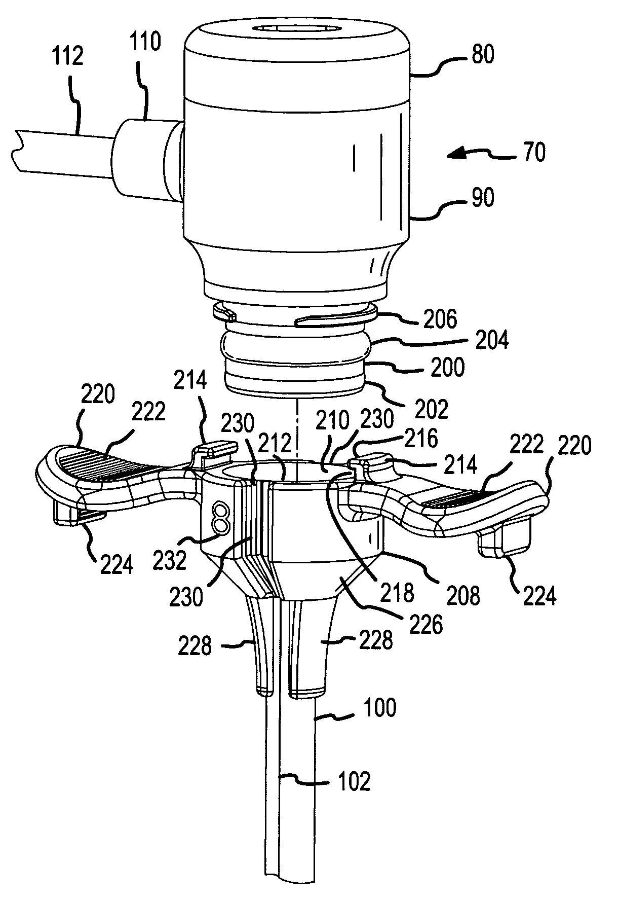
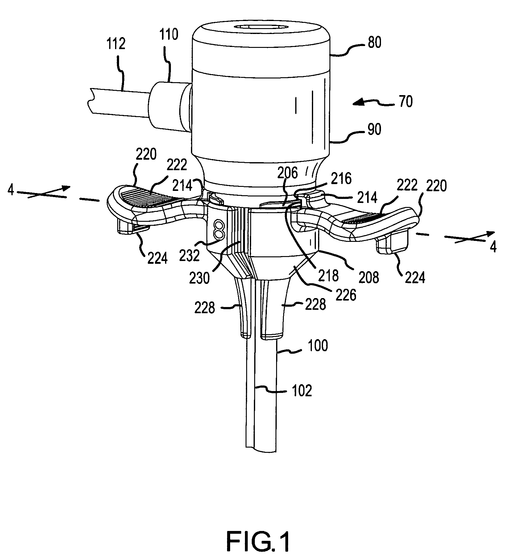
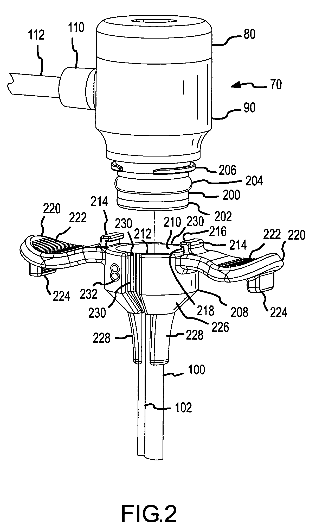
[0062]The following disclosure of the invention describes a hemostasis device and splittable sheath assembly designed for both attachment with and detachment from each other in a manner designed to reduce any force exerted on an indwelling lead. Several embodiments of the invention are disclosed herein. Common among the embodiments of the invention is the ability to disconnect the splittable sheath from the hemostasis device by merely splitting the sheath. No prior removal of the connection between the hemostasis device and the splittable sheath is required. Stated another way, while various structures and methodologies are employed as disclosed herein for attaching the hemostasis device to the splittable sheath, employing the reverse of these methodologies for disconnecting the hemostasis device from the splittable sheath is not required before the sheath is able to be split. The action of splitting the sheath simultaneously uncouples the splittable sheath from the hemostasis devic...


PUM


Abstract

A system for connecting a hemostasis valve to a splittable sheath includes an interface formed between a ledge on the proximal end of a cannula portion of the hemostasis valve and an engagement structure aligned with the handles of the splittable sheath. Pulling the handles to split the sheath likewise disengages the ledge from the engagement structure. A snap ring on the cannula portion engages a snap ring in the lumen of a sheath hub formed on the proximal end of the splittable sheath. An O-ring between the cannula portion and the sheath hub provides a fluid-tight seal.

Description

CROSS-REFERENCE TO RELATED APPLICATIONS[0001]This application claims priority pursuant to 35 §U.S.C. 119(e) to U.S. provisional application No. 60 / 485,783, filed 8 Jul. 2003, entitled Detachable Hemostasis Valve and Splittable Sheath Assembly, which is hereby incorporated by reference in its entirety as though fully set forth herein.BACKGROUND OF INVENTION[0002]a. Field of the Invention[0003]This invention relates generally to the field of medical instruments used for intra-arterial and intravenous introduction of instruments and more specifically to a connection assembly for creating a fluid seal connection between such medical instruments.[0004]b. Background Art[0005]There are a number of medical procedures which require the introduction of medical instruments into arteries and veins. In one such procedure, known as the Seldinger procedure, a surgical opening is made in a vein or artery with a needle. A guide wire is then inserted through the lumen of the needle into the vein or a...

Claims


Application Information

Patent Timeline
Patent Type & Authority Patents(United States)
IPC IPC(8): A61B19/00A61M5/178A61B17/00A61B17/34A61M25/06A61M39/06
CPCA61B17/3421A61M25/0668A61M39/0606A61B17/3415A61B17/3462A61B17/3498A61B2017/00477A61M2039/0633A61M2039/064A61M2039/066
Inventor POTTER, DANIEL J.STEHR, RICHARD E.
Owner ST JUDE MEDICAL ATRIAL FIBRILLATION DIV
Why Eureka
Try Eureka