
Light-emitting component

a technology of light-emitting components and components, which is applied in the direction of discharge tubes/lamp details, discharge tubes luminescnet screens, electric discharge lamps, etc., can solve the problems of not being very efficient, blue fluorescent emitters have a long life, etc., and achieve high efficiency

Active Publication Date: 2011-07-26
NOVALED GMBH
View PDF159 Cites 32 Cited by
  • Summary
  • Abstract
  • Description
  • Claims
  • Application Information

AI Technical Summary

Problems solved by technology

The problem that blue fluorescent emitters admittedly have a long lifetime but are not very efficient is overcome by virtue of the fact that triplet excitons which arise upon application of the electrical energy in the emitter which emits light predominantly in the blue or in the blue-green spectral range and which normally decompose non-radiatively are utilized for light emission in particular on account of the configuration of the triplet energy for the energy level of the triplet state of the fluorescent emitter in the emission layer and of the triplet energy for the energy level of the triplet state of the phosphorescent emitter in the further emission layer.

Method used


Image

  • Light-emitting component
  • Light-emitting component
  • Light-emitting component

Examples


first embodiment

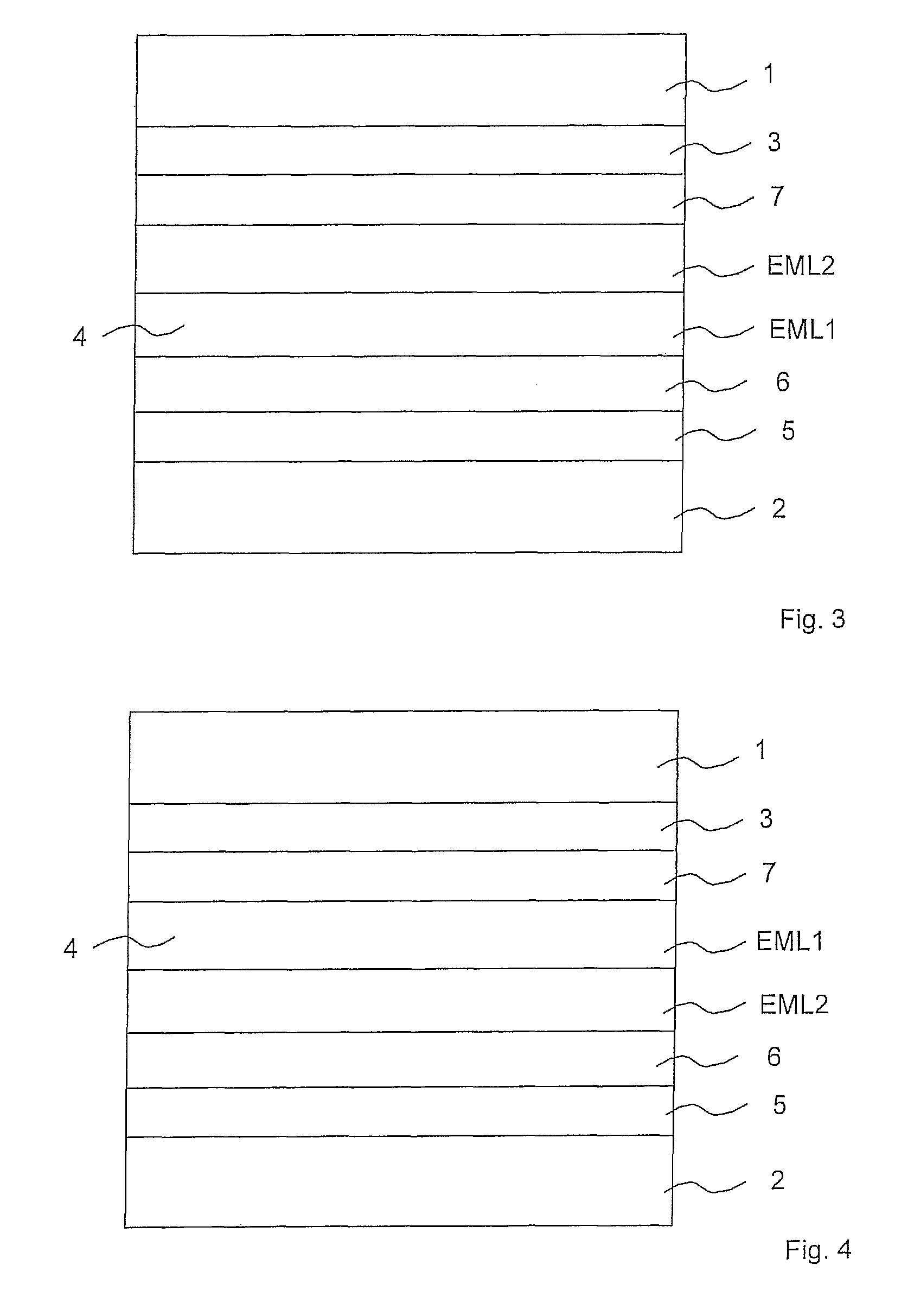
[0050]FIG. 3 shows a schematic illustration of a layer arrangement of an organic light-emitting diode in which a main recombination zone is formed in a targeted manner ;

second embodiment

[0051]FIG. 4 shows a schematic illustration of a layer arrangement of an organic light-emitting diode in which the main recombination zone is formed in a targeted manner ;

third embodiment

[0052]FIG. 5 shows a schematic illustration of a layer arrangement of an organic light-emitting diode in which the main recombination zone is formed in a targeted manner ;

[0053]FIG. 6 shows a CIE chromaticity diagram;

[0054]FIG. 7 shows a model spectrum for an emitter material emitting light in the blue spectral range;

[0055]FIG. 8 shows a diagram for comparison of the necessary blue emission light when generating white light for different light emissions in the green and red spectral ranges;

[0056]FIG. 9 shows an electroluminescence spectrum for an organic reference light-emitting diode;

[0057]FIG. 10 shows an electroluminescence spectrum for a first organic light-emitting diode according to the invention;

[0058]FIG. 11 shows an electroluminescence spectrum for a second organic light-emitting diode according to the invention; and

[0059]FIG. 12 shows structural formulae for molecules of an emitter material.

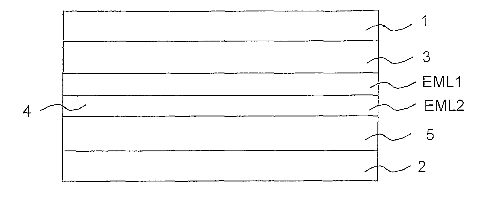
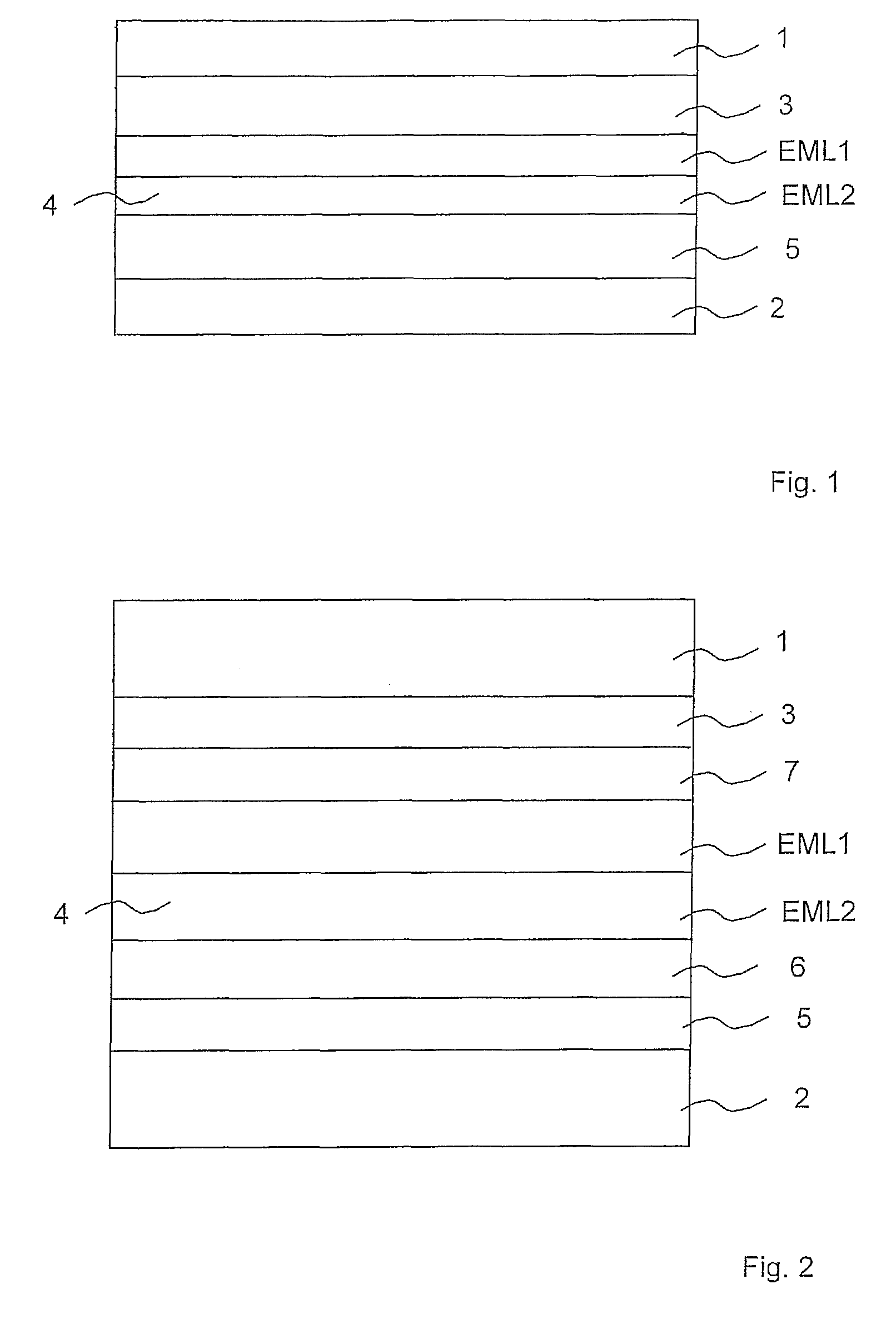
[0060]FIG. 1 shows a schematic illustration of a layer arrangement of an organic li...


PUM


Abstract

The invention relates to a light-emitting component, in particular organic light-emitting diode, having an electrode and a counterelectrode and an organic region—arranged between the electrode and the counterelectrode—with a light-emitting organic region, which comprises an emission layer and a further emission layer and which, upon application of an electrical voltage to the electrode and the counterelectrode, is formed in a manner emitting light in a plurality of colour ranges in the visible spectral range, optionally through to white light, in which case the emission layer comprises a fluorescent emitter which emits light predominantly in the blue or in the blue-green spectral range; the further emission layer comprises one or a plurality of phosphorescent emitters emitting light predominantly in the non-blue spectral range; a triplet energy for an energy level of a triplet state of the fluorescent emitter in the emission layer is greater than a triplet energy for an energy level of a triplet state of the phosphorescent emitter in the further emission layer; and an at least 5% proportion of the light generated in the light-emitting organic region is formed in the visible spectral range as fluorescent light from singlet states of the fluorescent emitter in the emission layer.

Description

[0001]The invention relates to a light-emitting component, in particular an organic light-emitting diode (OLED), having an electrode and a counterelectrode and an organic region—arranged between the electrode and the counterelectrode—with a light-emitting organic region, which comprises an emission layer and a further emission layer and which, upon application of an electrical voltage to the electrode and the counterelectrode, is formed in a manner emitting light in a plurality of colour ranges in the visible spectral range, optionally through to white light.PRIOR ART[0002]Increased attention has been given in recent years to organic light-emitting diodes which emit light in a plurality of colour ranges through to white light. It is generally recognized that this technology has a great potential for possible applications in the field of illumination technology. White organic light-emitting diodes are now reaching power efficiencies that lie in the region of conventional electrical i...

Claims


Application Information

Patent Timeline
Patent Type & Authority Patents(United States)
IPC IPC(8): H01J1/62H01J63/04
CPCH01L51/5016H01L51/5036H01L51/002H01L51/0051H01L51/0059H01L51/0062H10K71/30H10K85/611H10K85/649H10K85/631H10K50/125H10K50/11H10K2101/10
Inventor PFEIFFER, MARTINSCHWARTZ, GREGORMURANO, SVENBIRNSTOCK, JAN
Owner NOVALED GMBH
Learn More