Method and system for calculating and verifying the integrity of data in a data transmission system

integrity verification technology, applied in the field of methods and systems for calculating and verifying the integrity of data in a data transmission system, can solve problems such as discarding messages and inability to compute correctly

Active Publication Date: 2011-07-26
ZEBRA TECH CORP
View PDF6 Cites 962 Cited by
  • Summary
  • Abstract
  • Description
  • Claims
  • Application Information

AI Technical Summary

Benefits of technology

[0023]The invention also provides a means for a tag to reply to a reader request in a shortened or truncated form whilst still being able to provide the reader with a full error checking capability as if the entire message had been transmitted whether the checksum is calculated and stored on the tag when the tag is programmed or whether the checksum is generated ‘on the fly’ by the tag at the time of the tag sending a reply. This is particularly important when the tag is to contain user written data, where this data can be changed by the user. If the checksum were pre-calculated, and stored on the tag and user data subsequently changed the CRC would be incorrect. This would mean that the CRC could not be protected as it would have to be re-written each time that a user modified the data content. This invention therefore allows a portion of the tag data such as the ID to be locked and protected whilst giving users the freedom to change their data and yet still providing a valid and flexible CRC for over the air communications error checking whilst also retaining the flexibility of truncated messaging.

Problems solved by technology

Therefore in the latter case, when the reader tests the received message for correctness using the stored checksum or CRC, it will not compute correctly and will discard the message as being in error.

Method used


Image

  • Method and system for calculating and verifying the integrity of data in a data transmission system
  • Method and system for calculating and verifying the integrity of data in a data transmission system
  • Method and system for calculating and verifying the integrity of data in a data transmission system

Examples


Embodiment Construction

[0033]The invention will be described further, by way of example, with reference to the accompanying drawings, in which:

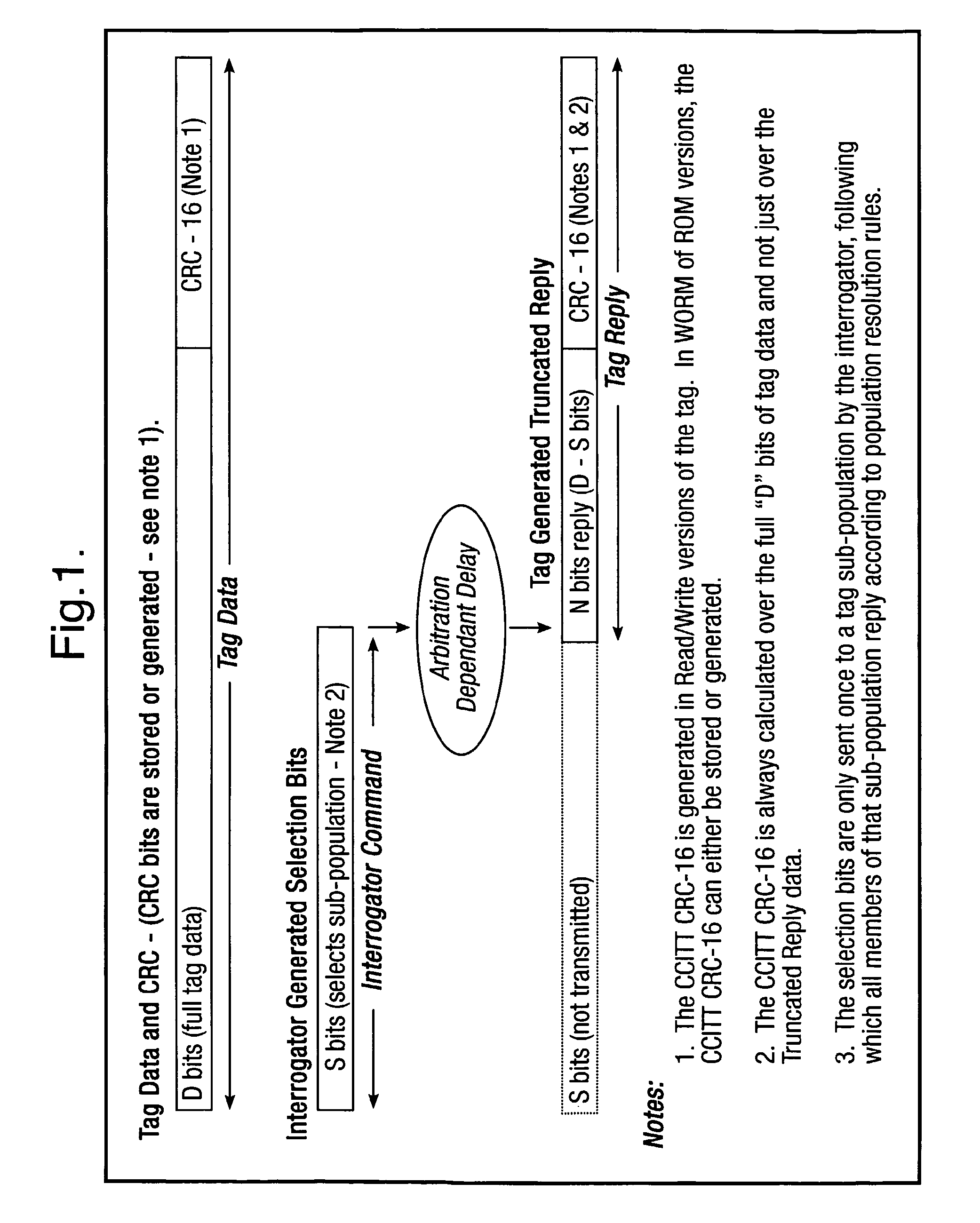
[0034]FIG. 1 illustrates a typical bit format for a tag identity and a portion of that bit identity used by an interrogator in its command to select a sub-population of tags;

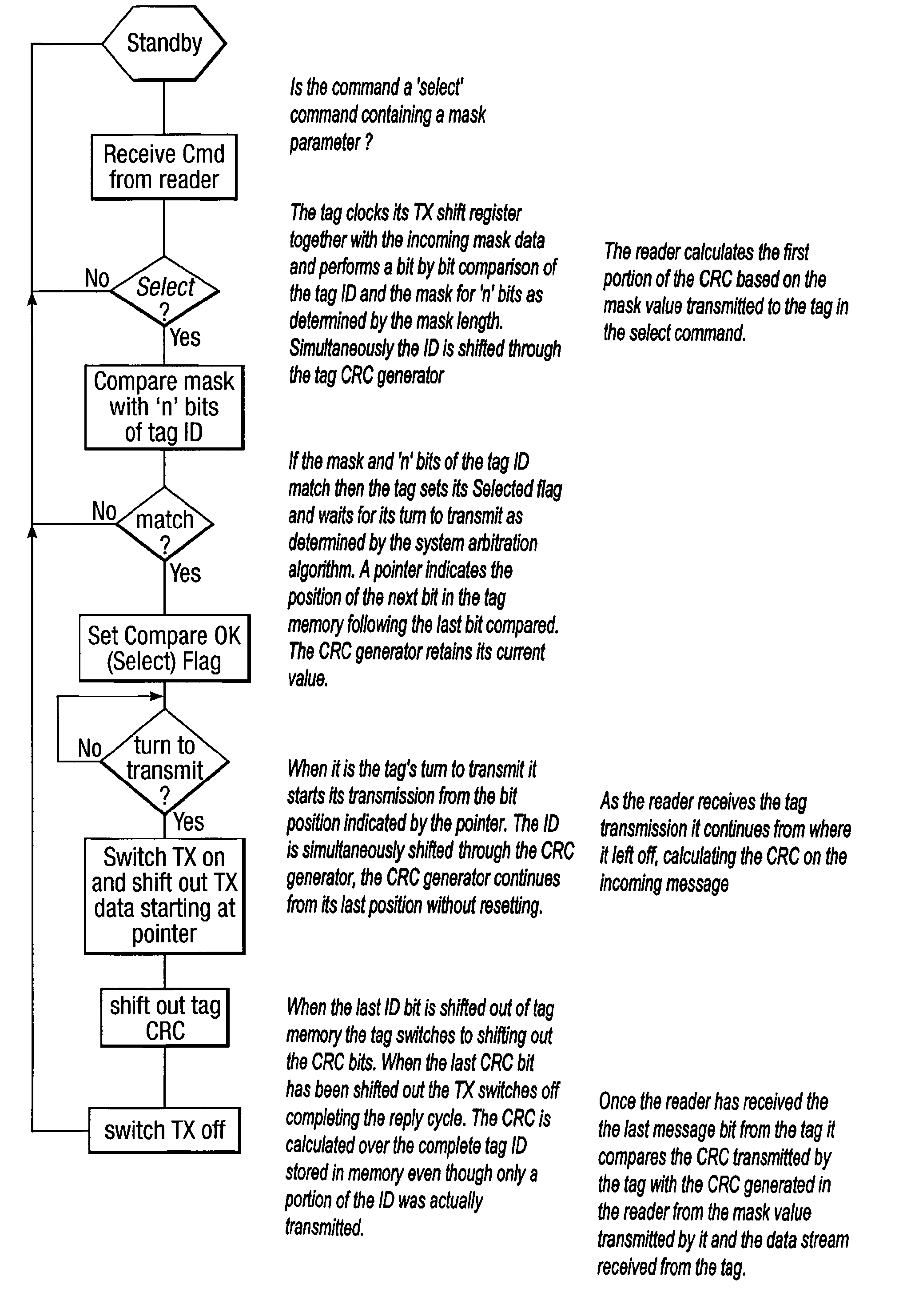
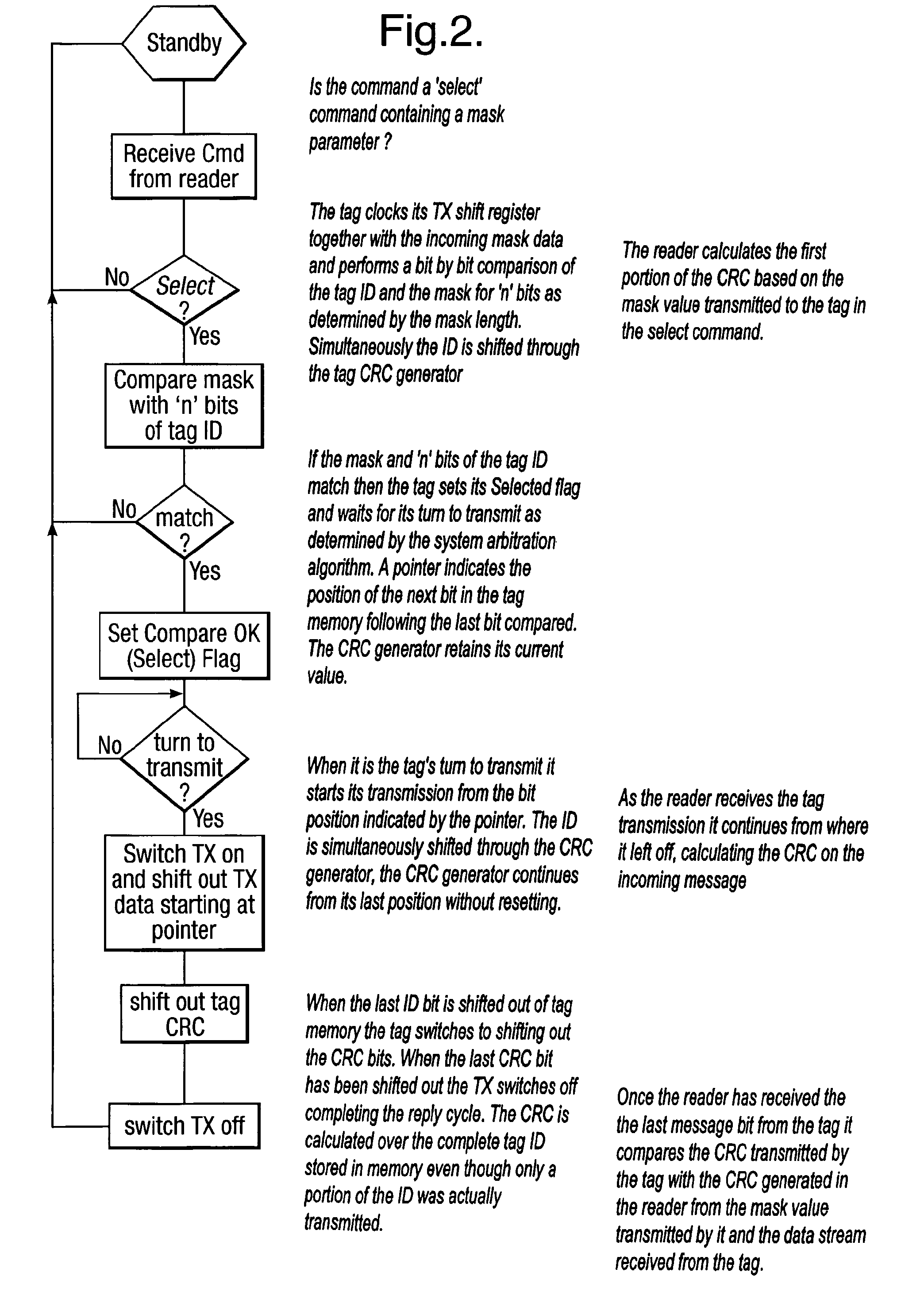
[0035]FIG. 2 shows a flow diagram of the command response sequence;

[0036]FIG. 3 shows the relative internal timing in the tag of the incoming command, the compare sequence and the transmitted tag message, together with the internal timing signals A, B, C and D and

[0037]FIG. 4 is a block diagram of a typical tag in accordance with one embodiment of the invention.

[0038]A typical RFID system comprises a reader and a plurality of tags, the reader issues a request command containing a mask for all tags present within the reader's illuminating field to reply if for example the first 16 bits of the tag identity match the 16 bits in the mask field contained within the reader's request command. The tags...


PUM


Abstract

A method is described of calculating and verifying the integrity of data in a data communication system. The system comprises a base station and one or more remote stations, such as in an RFID system. The method includes transmitting a select instruction from the base station to the one or more remote stations, the select instruction containing a data field which matches a portion of an identity or other data field in one or more of the remote stations; transmitting from a selected remote station or stations a truncated reply containing identity data or other data of the remote station but omitting the portion transmitted by the base station; calculating in the base station a check sum or CRC from the data field originally sent and the truncated reply data received and comparing the calculated check sum or CRC with the check sum or CRC sent by the remote station.

Description

[0001]The present invention relates to a method and system for calculating and verifying the integrity of data in a data transmission system and more particularly, but not exclusively, to data transmission systems over radio between a base station and one or more mobile or remote stations such as (but not limited to) those used in Radio Frequency Identification (RFID) Systems. The invention also provides a transponder or tag to implement the method.BACKGROUND[0002]A Radio Frequency Identification System is usually comprised of an interrogator (base station) commonly referred to as a reader or scanner and one or more transponders (mobile stations) usually called tags or electronic labels.[0003]In systems of known art, the reader issues a request or command for any tags within range to reply with their identity or their stored data. In a variant, tags on detecting the presence of a reader will send their identity or stored data. The identity or stored data is transmitted by the tag us...

Claims


Application Information

Patent Timeline
Patent Type & Authority Patents(United States)
IPC IPC(8): H03M13/00G06K7/00H03M13/09H04L1/00
CPCG06K7/0008H04L1/0061H03M13/09H03M13/03
Inventor TURNER, CHRISTOPHER GORDON GERVASEMCMURRAY, JOHN
Owner ZEBRA TECH CORP
Why Eureka
Try Eureka