Portable floating hot tub

a floating hot tub and portable technology, applied in the field of portable hot tubs, can solve the problems of not being economically feasible for remote locations to use portable hot tubs, not being able to provide extremely strong sidewalls, and being relatively sophisticated and expensive electronically monitored, so as to achieve convenient assembly, easy entry and exit, and comfortable seating

Inactive Publication Date: 2011-08-02
WEST PAUL E
View PDF12 Cites 24 Cited by
  • Summary
  • Abstract
  • Description
  • Claims
  • Application Information

AI Technical Summary

Benefits of technology

[0008]In general, the present invention provides a hot tub that is portable, easily assembled, easy to enter and exit, provides for comfortable seating, and can be used in environments where there is cold and turbulent water. The hot tub has a collapsible, rigid frame that makes it operable in turbulent water such as in a river or on the ocean. Walls of the hot tub are constructed from a thermally insulating material so that it retains heat and can be operated in cold water environments found in lakes, rivers and oceans. The hot tub is portable and can be carried and assembled easily by a single individual in confined environments such as on a boat or on the dock. Finally, the rigid flame structure of the tub provides for comfortable seating.
[0009]In one embodiment, the hot tub is constructed from three independent components: a pontoon, a frame and walls. The hot tub is supported in the water by a floating inflatable pontoon. The pontoon can be constructed from one or more bladder units. The pontoon must be large enough to stabilize the tub when people enter or leave the tub. The support frame of the tub is made with structural materials such as pipes or rods, or any other structural material that may be easily disassembled. The frame may include provisions for seating of one or more people in the hot tub. Extra material may be placed between the frame arms and the pontoon to distribute the weight of the frame on the pontoon. The walls of the hot tub are made from a thermally insulating material such as neoprene rubber. The insulating material helps to keep the water in the tub from losing heat too rapidly to the external body of water. When the hot that is filled with water, the majority of the tub is submerged below the surface of the external body of water, providing stability. The hot tub is designed such that when filled with water, the water level inside the tub is approximately the same level as the external body of water.

Problems solved by technology

The conventional hot tub is mounted in or above the ground, has rigid sidewalls, typically a molded fiberglass shell for containing water, and a relatively sophisticated and expensive electronically monitored and controlled water heating system relatively permanently connected an existing water supply system.
To date, there has not been an economically feasible portable hot tub for use in remote locations away from the backyard.
One difficult hurdle in constructing a portable hot tub is the necessity of providing extremely strong sidewalls to contain the large amount of water therein.
Of course providing sturdy sidewalls increases the size and weight of the device which hinders portability.
One possible answer to this practical problem is to immerse the hot tub in a larger body of water, which equilibrates the hydraulic forces across the spa wall and therefore reduces the structural strength requirements.
For a number of reasons, these designs lack one or more of the following: easy portability, easy and rapid setup, stability in turbulent water, or economic practicality.
Some relatively recent floating hot tubs, such as in U.S. Pat. No. 6,795,983, commercially available as the HOT POD floating spa, are primarily designed for use in a pool with relatively flexible and lightweight construction, which makes them ill-suited for use in very cold and turbulent water.
Though technically “floating,” these hot tubs are not portable by themselves, and are relatively permanently structurally installed and connected to the electrical and water systems of the boat.

Method used


Image

  • Portable floating hot tub
  • Portable floating hot tub
  • Portable floating hot tub

Examples


Embodiment Construction

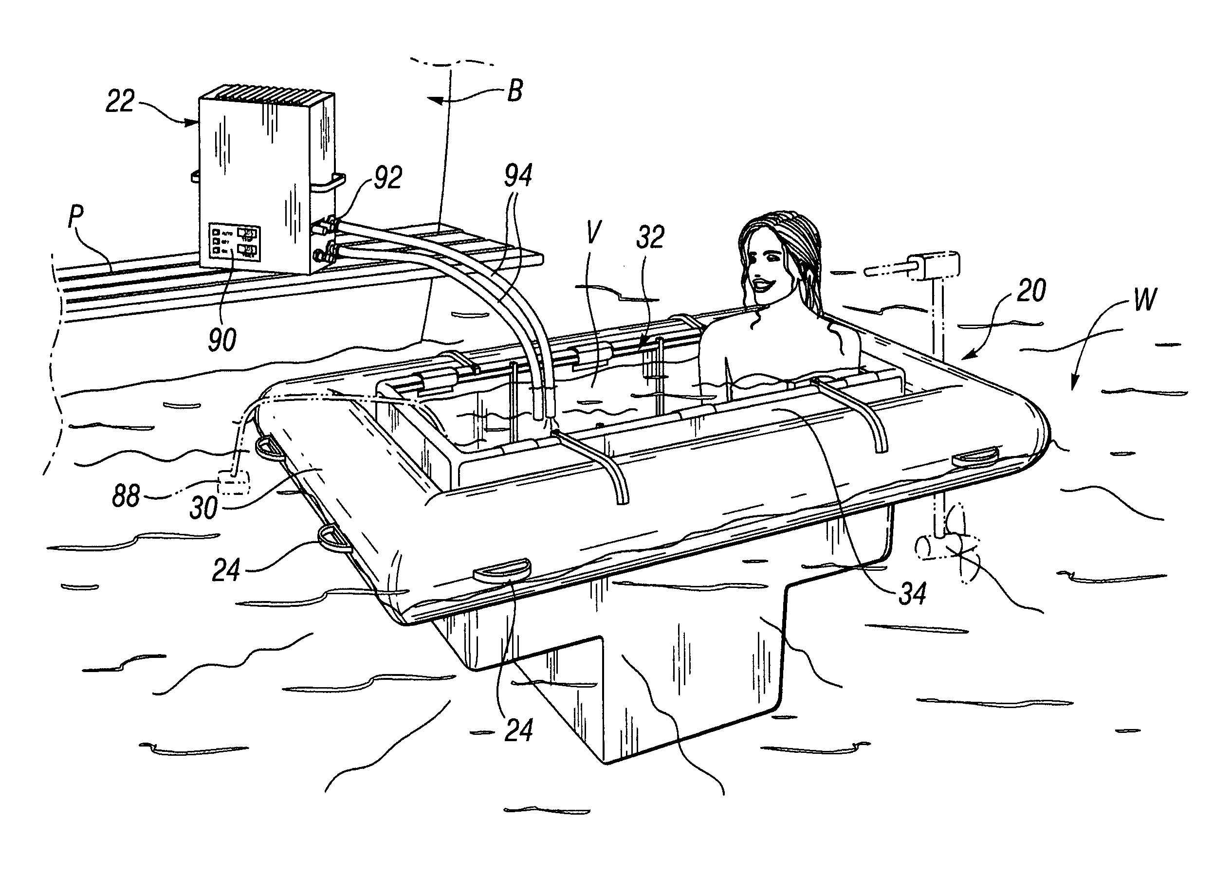
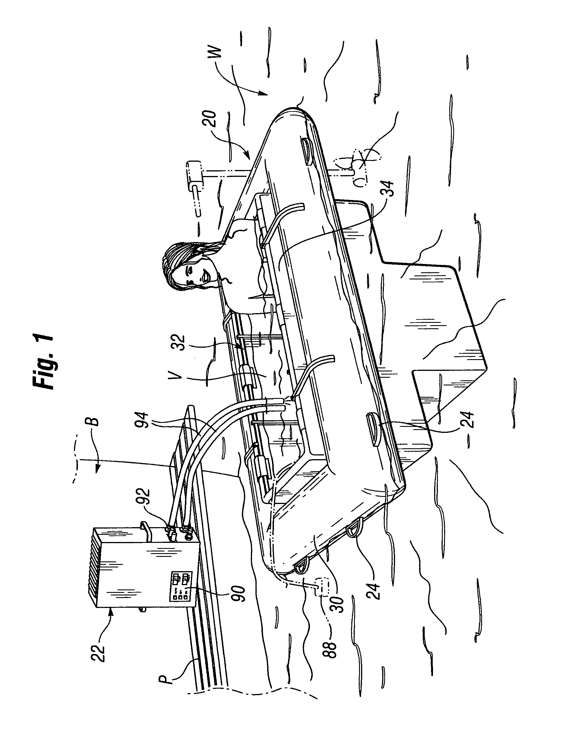
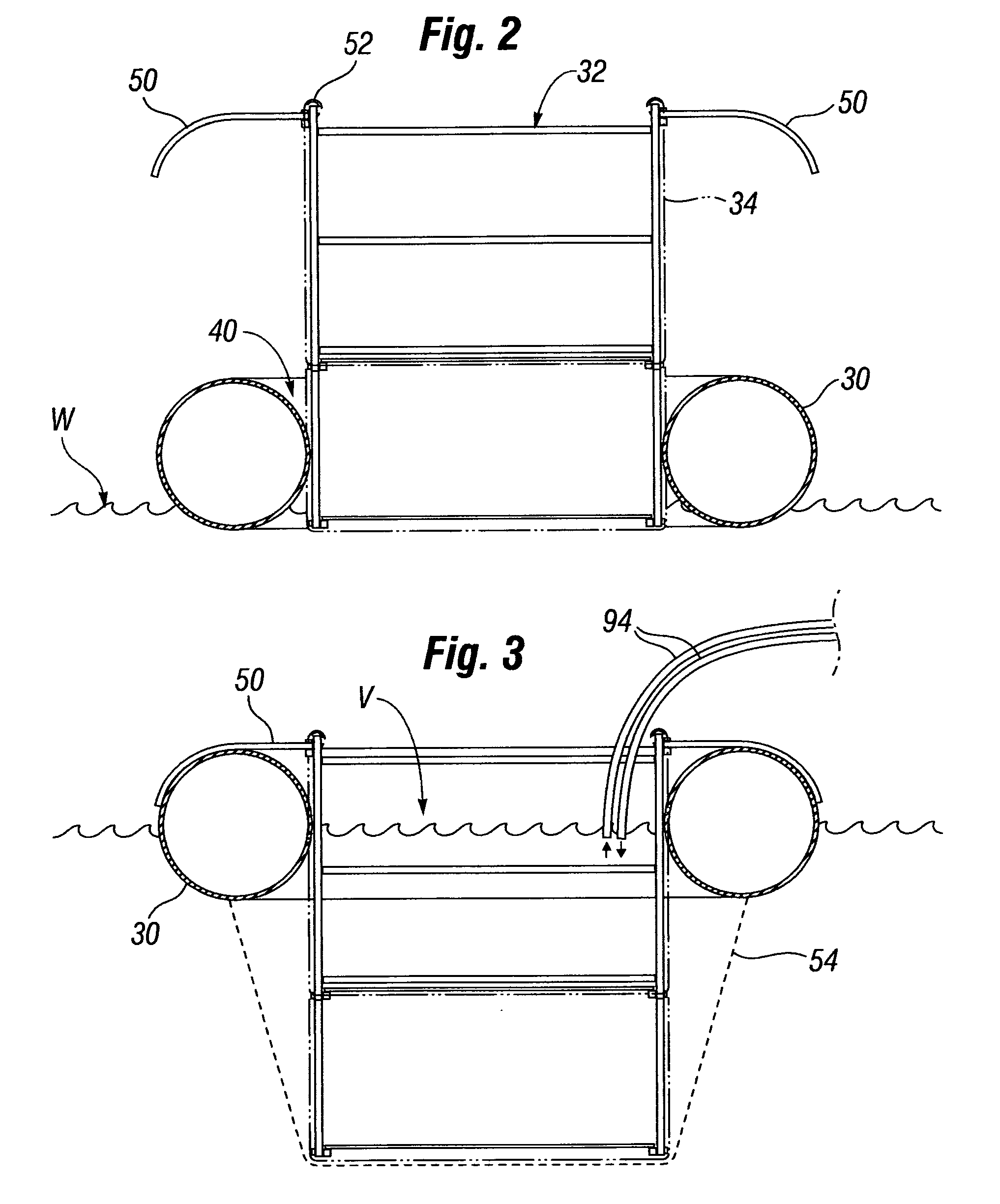
[0037]The present invention provides a portable floating hot tub that is an improvement over previous designs. The exemplary hot tub of the present invention is easy to set up and take down by one person in any confined space and in a short amount of time, is stable in even choppy waters, and retains heat for a significant length of time. Moreover, the components of the hot tub can be carried in two small luggage-sized bags that are easily transported and stored in a small space. A number of desirable features described herein combine to provide a truly advanced portable floating hot tub, though it should be understood that certain features by themselves and some combinations thereof are believed novel and may be incorporated into other portable floating hot tubs for a similar advantage. Therefore, the present invention should not be considered limited to the exemplary system described herein, but instead should be evaluated by reference to the appended claims.

[0038]The 1 illustrate...


PUM

PropertyMeasurementUnit
weightaaaaaaaaaa
inner volumeaaaaaaaaaa
diameteraaaaaaaaaa

Abstract

A portable floating hot tub that is easy to assemble and take down and can be used in environments with extremely cold and turbulent water. The hot tub has three main components: a collapsible frame made of connected rigid members, an insulated liner sized and shaped to closely fit against the deployed frame and form a subassembly, and an inflatable pontoon that may have a central aperture for receiving the subassembly. The pontoon is first inflated and placed on the body of water, after which the frame and liner subassembly are placed over the central aperture. Filling the internal volume defined by the insulated liner with water causes the subassembly to descend within the pontoon. Cooperating means on the subassembly and / or pontoon prevent the subassembly from passing completely through the central aperture. A source of heated water such as a portable heater having a heating capacity of at least 30,000 BTUs rapidly heats up the water within the hot tub. The system components can be transported in one or more carry bags of less than 100 pounds and deployed and taken down by one person in an extremely small space, such as on a boat.

Description

RELATED APPLICATIONS[0001]This application claims priority under 35 U.S.C. §119 to U.S. Provisional Application No. 60 / 903,567, filed Feb. 27, 2007.FIELD OF THE INVENTION[0002]The present invention relates to a portable hot tub that floats in a body of water and, in particular, to an easily and rapidly deployable, portable floating hot tub that can be used in bodies of water that are turbulent and cold.BACKGROUND OF THE INVENTION[0003]Hot tubs or spas are excellent ways for relaxing and rejuvenating, as well as therapeutically soothing sore muscles and body parts. The conventional hot tub is mounted in or above the ground, has rigid sidewalls, typically a molded fiberglass shell for containing water, and a relatively sophisticated and expensive electronically monitored and controlled water heating system relatively permanently connected an existing water supply system. Hot tubs are often combined with standard swimming pools, either close to but spaced from the pool or immediately a...

Claims


Application Information

Patent Timeline
Patent Type & Authority Patents(United States)
IPC IPC(8): A47K3/06
CPCE04H4/0012Y10T29/49904Y10T29/49826
Inventor WEST, PAUL E.
Owner WEST PAUL E
Why Eureka
Try Eureka