Transmission

a technology of transmission and transmission shaft, which is applied in the field of transmission, can solve the problems of increasing the overall length of the combination of engine and transmission shaft, difficulty in adequately laying out the power train in the engine compartment of the vehicle, and the inability to downsize the second countershaft, so as to reduce the driving torque and facilitate the downsizing of the transmission

Inactive Publication Date: 2011-08-02
MAZDA MOTOR CORP
View PDF10 Cites 19 Cited by
  • Summary
  • Abstract
  • Description
  • Claims
  • Application Information

AI Technical Summary

Benefits of technology

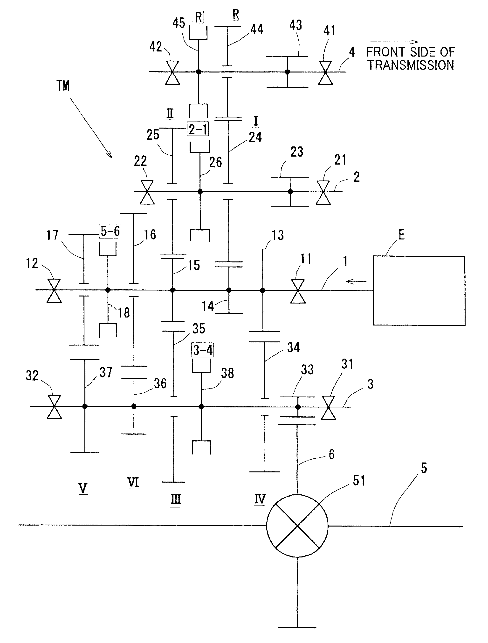
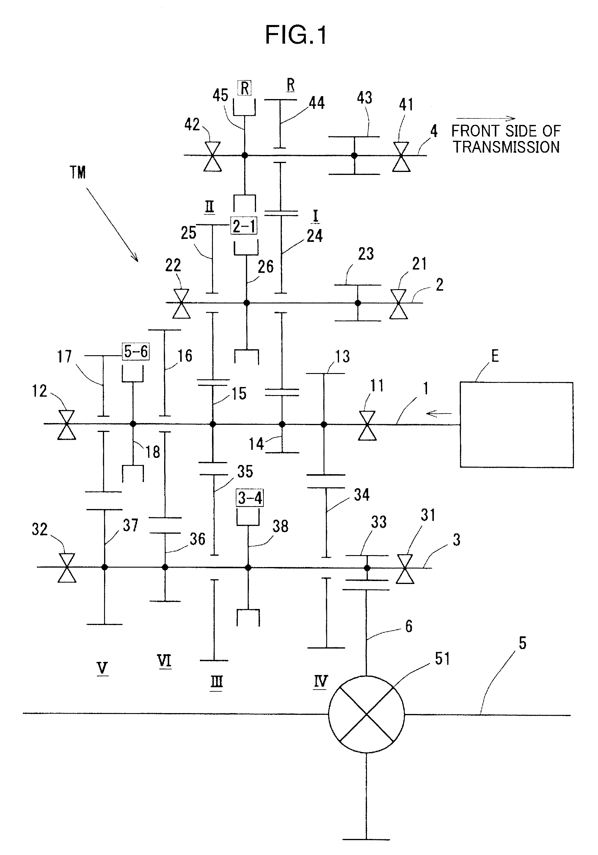
[0016]In view of the above circumstances, the present invention is directed to a transmission which comprises an input shaft, three auxiliary shafts, such as a first countershaft, a second countershaft and a reverse shaft, and a differential driving gear provided on each of the auxiliary shafts and adapted to drive a differential ring gear, and it is an object of the present invention to provide a technique capable of minimizing the number of speed-change driven gears on the first countershaft to ensure a layout space in an engine compartment of a vehicle, and reducing a driving torque to be applied to the second countershaft to facilitate downsizing of the transmission.
[0018]In the transmission of the present invention, only two speed-change driven gears are provided on the first countershaft, so that the first countershaft can be reduced in length. In addition, the first-speed and second-speed driven gears to be subjected to a relatively large driving torque are selected as the two speed-change driven gears, so that the second countershaft becomes free from undergoing such a large driving torque.
[0020]Even though the first-speed driven gear and the second-speed driven gear are provided on the first countershaft, there is no need to increase in size of a bearing for supporting the first countershaft, because the first countershaft can be reduced in length, and therefore a support span of the first countershaft can be reduced.
[0021]As above, according to the present invention, in a transmission comprising an input shaft, three auxiliary shafts, such as the first countershaft, the second countershaft and the reverse shaft, and a plurality of differential driving gears each provided on a corresponding one of the auxiliary shafts and adapted to drive a differential ring gear, the number of speed-change driven gears on the first countershaft can be minimized to ensure a layout space in an engine compartment of a vehicle, and a driving torque to be applied to the second countershaft can be reduced to facilitate downsizing of the transmission.

Problems solved by technology

In reality, a design aiming to increase the number of speed stages in the transverse transmission involves an increase in the number of speed-change gears, which leads to an increase in overall length of a combination of an engine and a transmission (i.e., Powertrain) and cause difficulty in adequately laying out the power train in an engine compartment of a vehicle.
Thus, there is a problem that the second countershaft cannot be downsized.
Moreover, a relatively large support span (i.e., bearing distance) of the second countershaft gives rise to another need for increasing support stiffness of a bearing for supporting the second countershaft to cause a problem about an increase in size of the bearing.

Method used


Image

  • Transmission
  • Transmission
  • Transmission

Examples


Embodiment Construction

[0028]With reference to the drawings, the present invention will now be described based on an embodiment thereof.

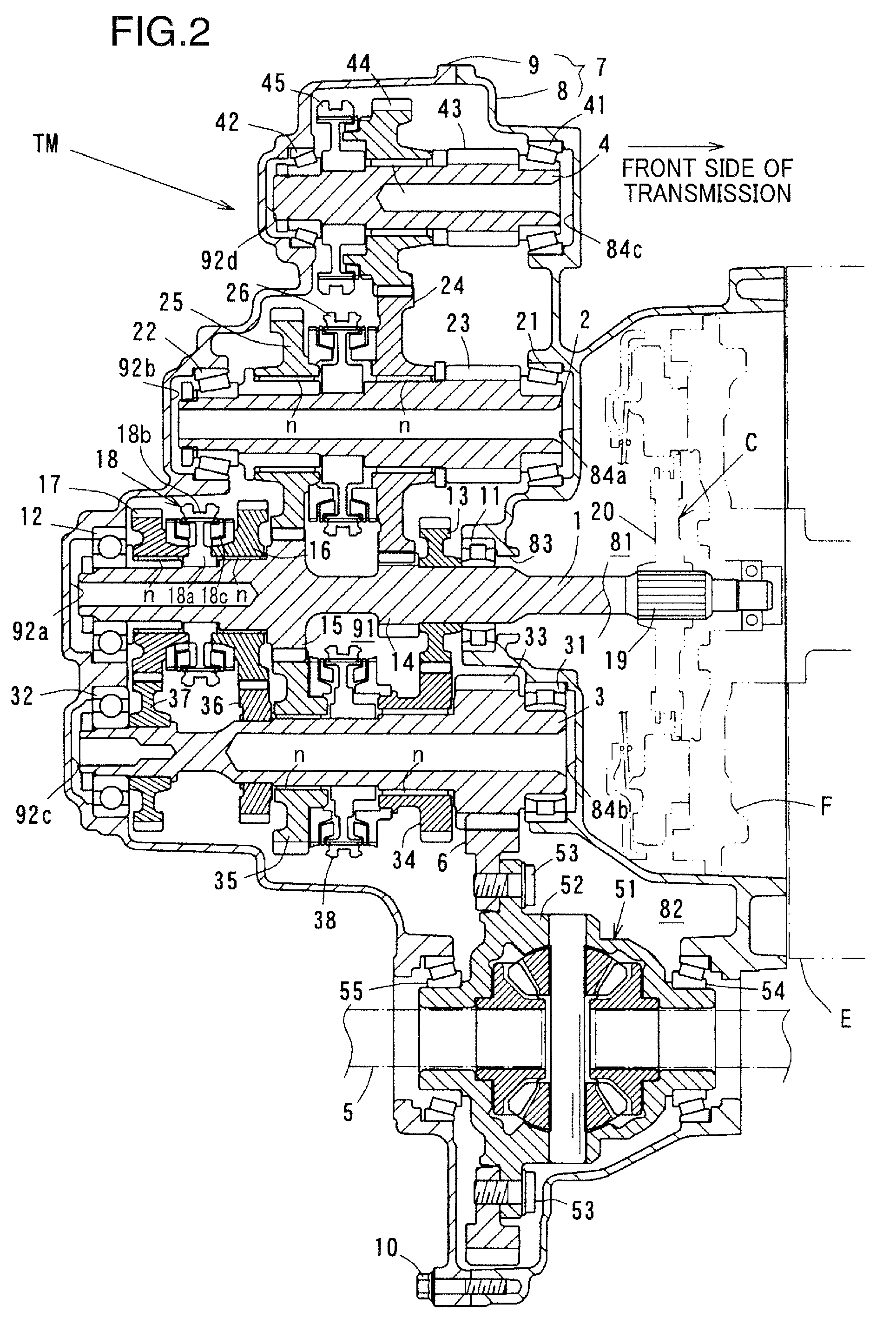
[0029]A geartrain of a transmission according to one embodiment of the present invention will be firstly described with reference to FIG. 1, which is a skeletal diagram showing the geartrain of the transmission. In the following description, a near side of the transmission with respect to an engine E will be referred to as “front or front side” in terms of the transmission or any component of the transmission, and a far side of the transmission with respect to the engine E, i.e., a side of the transmission opposite to the near side, will be referred to as “rear or rear side” in terms of the transmission or any component of the transmission”.

[0030]The transmission TM according to this embodiment is a so-called “transverse manual transmission” of a multi-shaft type having a plurality of shafts, which is designed to achieve six frontward speed stages and one reverse speed st...


PUM


Abstract

The present invention is directed to a transmission capable of minimizing the number of speed-change driven gears on a first countershaft to ensure a layout space in an engine compartment of a vehicle, and reducing a driving torque to be applied to a second countershaft to facilitate downsizing of the transmission. In the transmission, the first countershaft 2 is arranged at a position above an input shaft 1, and a first-speed driven gear 14 and a second-speed driven gear 24 are provided on the first countershaft 2.

Description

BACKGROUND OF THE INVENTION[0001]1. Field of the Invention[0002]The present invention relates to a transmission, and more particularly to a transmission designed to achieve six forward speed stages and one reverse speed stages, wherein an input shaft and an output shaft (countershaft) are disposed on respective different axes.[0003]2. Description of the Related Art[0004]Heretofore, as a transmission intended to be disposed on a lateral side of a transversely disposed engine (i.e., transverse engine), a so-called “transverse transmission” has been commonly employed which is designed such that an input shaft and an output shaft (countershaft) are disposed in parallel on respective different axes, and a plurality of speed-change gear sets are disposed between the input shaft and the output shaft (countershaft).[0005]In view of improvement in drive feeling, there exists a strong need for the transverse transmission to further increase the number of speed stages, as with other types of t...

Claims


Application Information

Patent Timeline
Patent Type & Authority Patents(United States)
IPC IPC(8): F16H3/08
CPCF16H3/093Y10T74/19233F16H2200/0052F16H2003/0931
Inventor OKADOME, YASUKIKUWAHARA, WATARUSHIRAISHI, MASARU
Owner MAZDA MOTOR CORP
Why Eureka
Try Eureka