Wing tip device

a technology of wing tip and wing tip, which is applied in the field of aircraft, can solve the problems of dictating the weight of the wing, significant increases in the wing root bending moment, etc., and achieves the effect of reducing the wing tip twisting, effective sweeping of the device, and increasing the wing loading

Inactive Publication Date: 2011-08-02
AIRBUS OPERATIONS LTD
View PDF21 Cites 44 Cited by
  • Summary
  • Abstract
  • Description
  • Claims
  • Application Information

AI Technical Summary

Benefits of technology

[0007]The present invention thereby provides an aircraft which can benefit from the drag reduction afforded by the wing tip device whilst not suffering too great an increase in bending moment in the wing, particularly at the wing root. Preferably the bending moment in the wing, and particularly at the wing root, during use is, in fact, reduced by the presence of the wing tip device.
[0011]Advantageously the majority of the wing tip device is in the form of a generally downwardly extending portion. Preferably the downwardly extending portion and the remainder of the wing tip device, meet at a junction, wherein the junction is open. As will be understood by the person skilled in the art, a junction is to be regarded as open if the change in angle from a portion on one side of the junction to a portion on the other side of the junction is more than 90 degrees. An open junction is thought to be particularly beneficial as it generates a low viscous drag.
[0017]It is thought that a generally downwardly extending device has an improved roll-up characteristic, in that the tip vortex core tends to be more outboard during use, than on the equivalent upwardly extending device.
[0018]The chord of the wing tip device at the proximal end is preferably the same as the chord of the wing at the wing tip. The chord of the wing tip device preferably decreases between the proximal end and the distal end. Advantageously the wing tip device has a relatively small average chord, thereby causing a relatively low friction drag to be created during flight.
[0023]Advantageously the wing tip device leading edge is swept. Preferably the sweep of the wing tip device is equal to the sweep of the wing. On a conventional aircraft, when the wing loading increases, the twist of the wing tip tends to decrease due to aeroeleastic deformation of the wing. Thus, on an aircraft according to the present invention having similar aeroelastic wing behaviour, when the wing loading is increased, the effective sweep of the device (which is downwardly extending) increases, reducing its lift curve slope relative to a rigid wing. Therefore as the wing distorts aeroelastically, the loads generated by the wing tip device tend to decrease, reducing the maximum load on the wing tip device during a high load manoeuvre. This is beneficial for a number of reasons. For example, the loads on the outer wing structure may be kept within an acceptable level during high load manoeuvres, and the potential penalty due to the tip device becoming inclined at a cant of less than 180 degrees during such a manoeuvre is reduced.
[0024]The aeroelastic behaviour of the aircraft of the present invention may also provide other benefits. Preferably the wing and / or wing tip device deforms, during use, to provide the aircraft with a larger span in comparison to when the aircraft is stationary on the ground, thereby reducing the induced drag encountered by the aircraft.

Problems solved by technology

The increase in lift can lead to significant increases in the wing root bending moment.
This in turn may dictate the weight of the wing.

Method used


Image

  • Wing tip device
  • Wing tip device
  • Wing tip device

Examples


Embodiment Construction

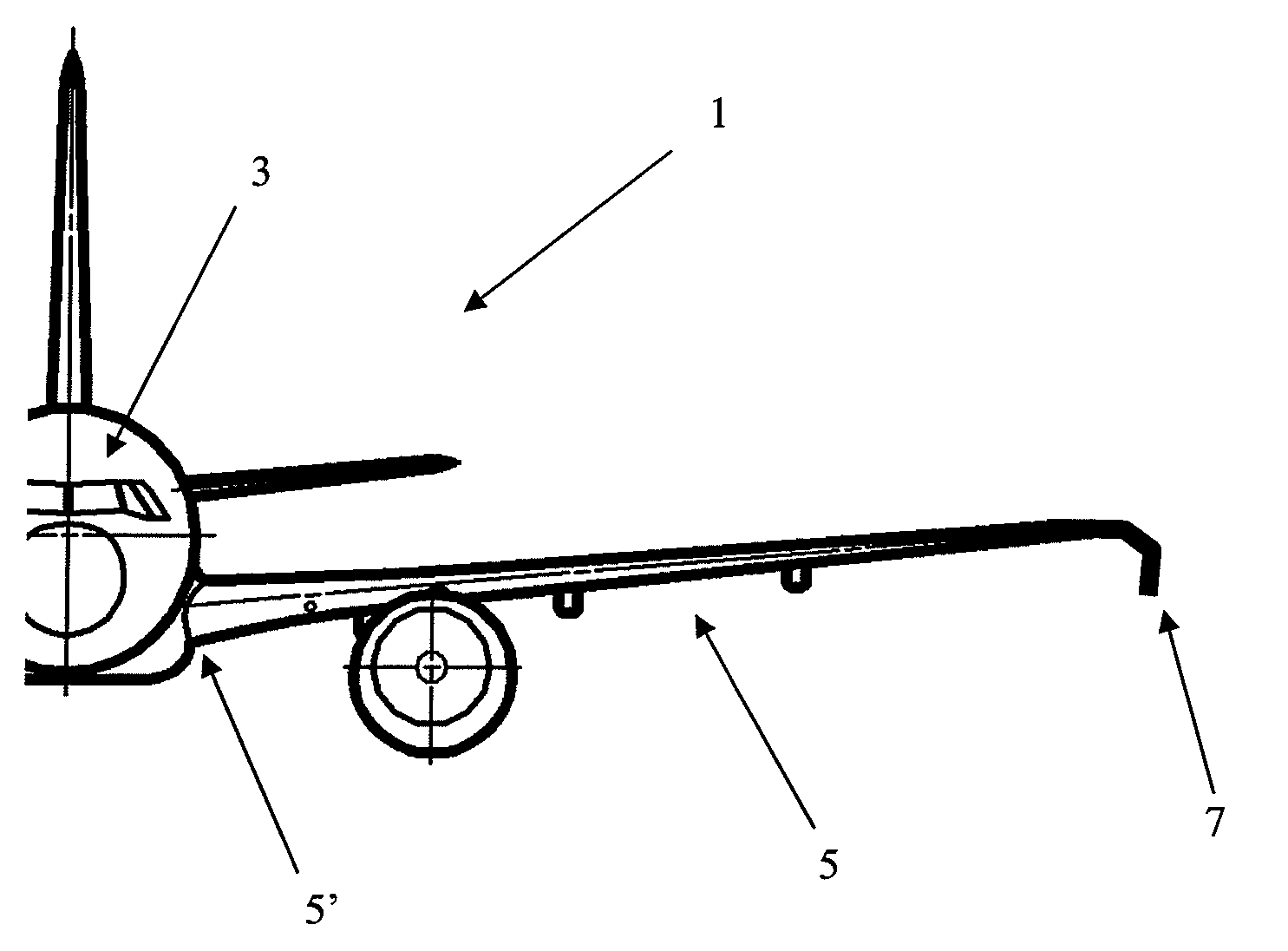
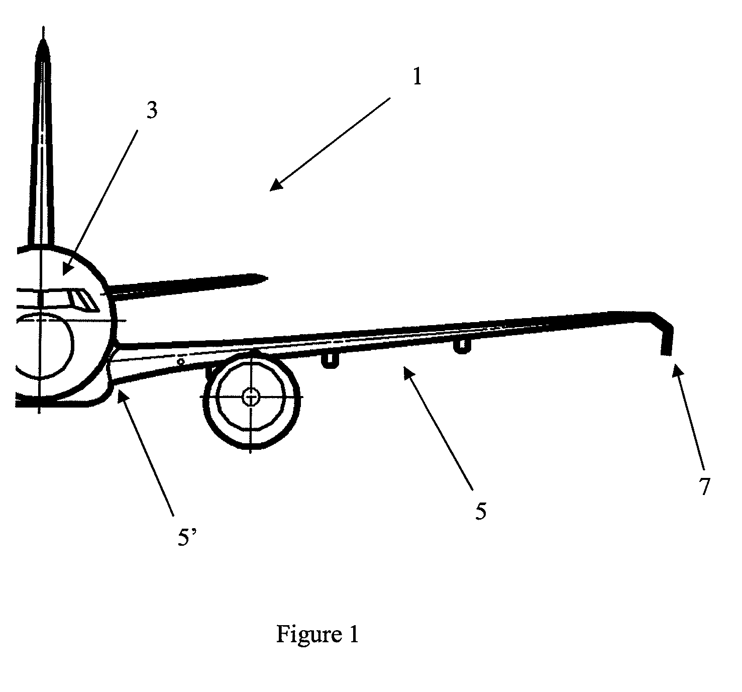
[0036]FIG. 1 is a front view of one half of an aircraft 1 according to a first embodiment of the invention. The aircraft comprises a fuselage 3, a wing 5 having a positive dihedral of seven degrees, and a wing tip device 7 located at the tip of the wing 5. The aircraft is shown flying at cruise speed in horizontal flight.

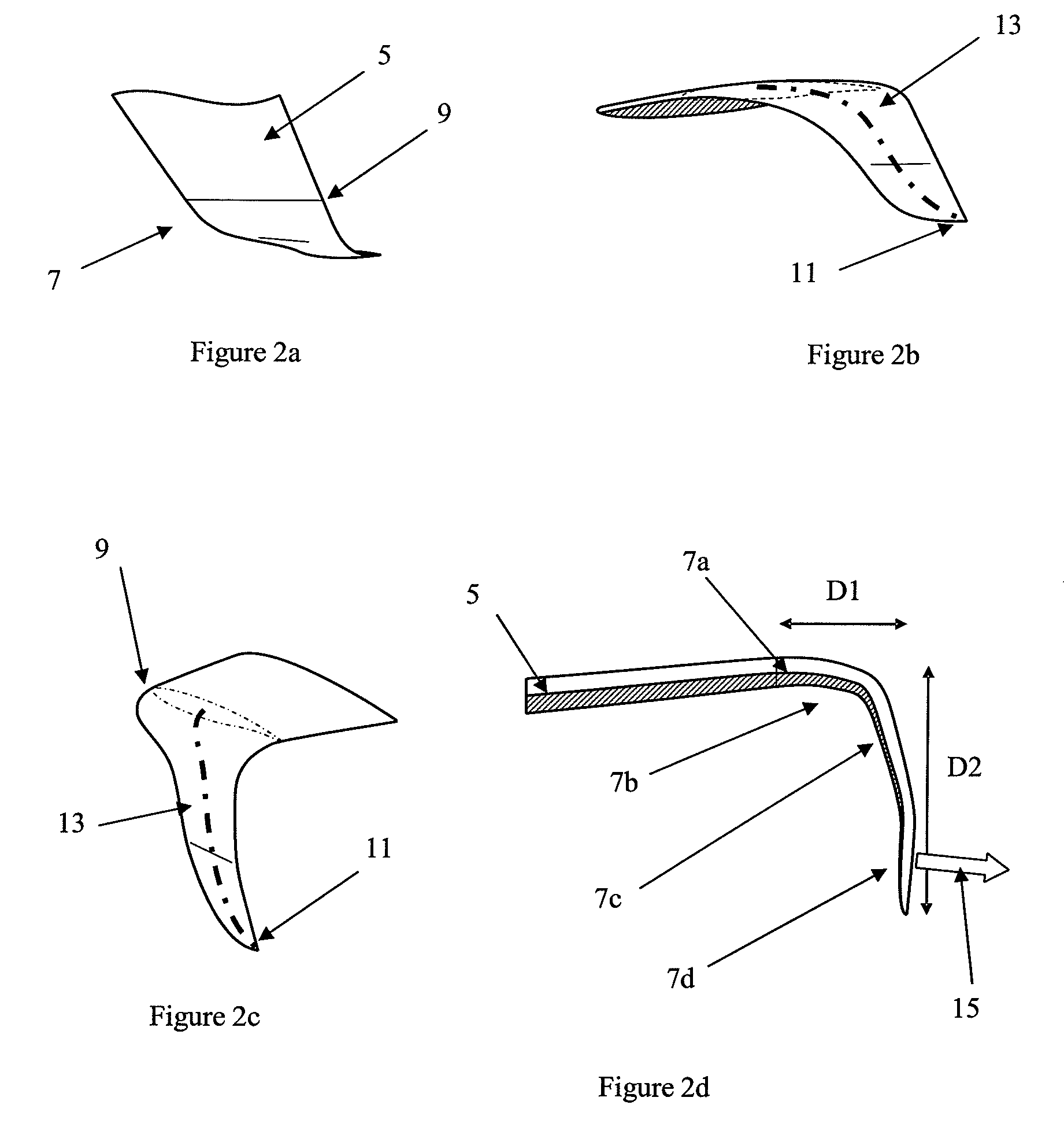
[0037]Referring to FIGS. 2a to 2d, the wing tip device 7 comprises a proximal end 9 and a distal end 11. The wing tip device 7 is connected to the wing 5 at the proximal end 9. At the proximal end the device is contiguous to the tip of the wing 5, and the respective chord lengths of the wing 5 and the wing tip 7 at this location are equal. The wing tip device 7 is thus blended with the wing 5.

[0038]According to the first embodiment the wing tip device has been retrofitted onto the aircraft, replacing a previous tip device. The connection (not shown) between the device 7 and the wing 5 is such that the device will shear off if it hits a foreign object with sufficient...


PUM


Abstract

An aircraft includes a wing having a positive dihedral, the wing having a tip and a wing tip device mounted in the region of the tip. The wing tip device is generally downwardly extending and has a region inclined at a cant of more than 180 degrees. The region is arranged to generate lift during flight. The region inclined at a cant of more than 180 degrees may be located at the distal end of the wing tip device. The wing tip may be swept and may aeroelastically deform during flight.

Description

RELATED APPLICATIONS[0001]The present application is based on International Application Number PCT / GB2006 / 003373 filed Sep. 12, 2006, and claims priority from British Application Number 0518755.4 filed Sep. 14, 2005, the disclosures of which are hereby incorporated by reference herein in their entirety.BACKGROUND OF THE INVENTION[0002]The present invention relates to aircraft and more particularly to wing tip devices for use on an aircraft.[0003]The use of wing tip devices, such as winglets and fences, on aircraft is well known. Such devices seek to improve the aerodynamic performance of the aircraft, in particular by reducing drag and increasing lift.[0004]The increase in lift can lead to significant increases in the wing root bending moment. The maximum bending moment to which a wing is expected to be subjected is likely to dictate the required strength of the wing. This in turn may dictate the weight of the wing. Thus, the gains in aerodynamic performance attained by adding a win...

Claims


Application Information

Patent Timeline
Patent Type & Authority Patents(United States)
IPC IPC(8): B64C23/06
CPCB64C23/065Y02T50/164B64C23/069Y02T50/10
Inventor MANN, ALAN
Owner AIRBUS OPERATIONS LTD
Why Eureka
Try Eureka