Apparatus and method for use on aircraft with spanwise flow inhibitors

a technology of spanwise flow inhibitor and apparatus, which is applied in the field of aircraft, can solve the problems of increasing the bending moment of the wing during flight, increasing the frequency of inspection and routine maintenance, and fatigue of the wing structure or wing box, so as to reduce the stress of the wing, increase the bending moment, and reduce the effect of payload

Inactive Publication Date: 2009-12-10
DESROCHE ROBERT J
View PDF5 Cites 48 Cited by
  • Summary
  • Abstract
  • Description
  • Claims
  • Application Information

AI Technical Summary

Benefits of technology

[0006]Some embodiments disclosed herein include the realization that wings can have one or more gurney flaps to counteract the increase in bending moment induced by wing extensions (e.g., wing tip extensions), spanwise flow inhibitors (e.g., wingtip fences, winglets, endplates, and the like), payload increases, and the like. The gurney flaps can extend from the wing proximate or at the trailing edge thereof. The gurney flaps can be fixed to a movable control surface or fixed to a stationary portion o

Problems solved by technology

Wingtip fences typically move the center of lift outwardly towards the wingtip, thus increasing wing bending moments during flight.
This increased bendi

Method used


Image

  • Apparatus and method for use on aircraft with spanwise flow inhibitors
  • Apparatus and method for use on aircraft with spanwise flow inhibitors
  • Apparatus and method for use on aircraft with spanwise flow inhibitors

Examples


Embodiment Construction

[0050]In the following description, certain specific details are set forth in order to provide a thorough understanding of various embodiments of the invention. However, one skilled in the art will understand that the invention may be practiced without these details.

[0051]Unless the context requires otherwise, throughout the specification and claims which follow, the word “comprise” and variations thereof, such as, “comprises” and “comprising” are to be construed in an open, inclusive sense, that is as “including, but not limited to.”

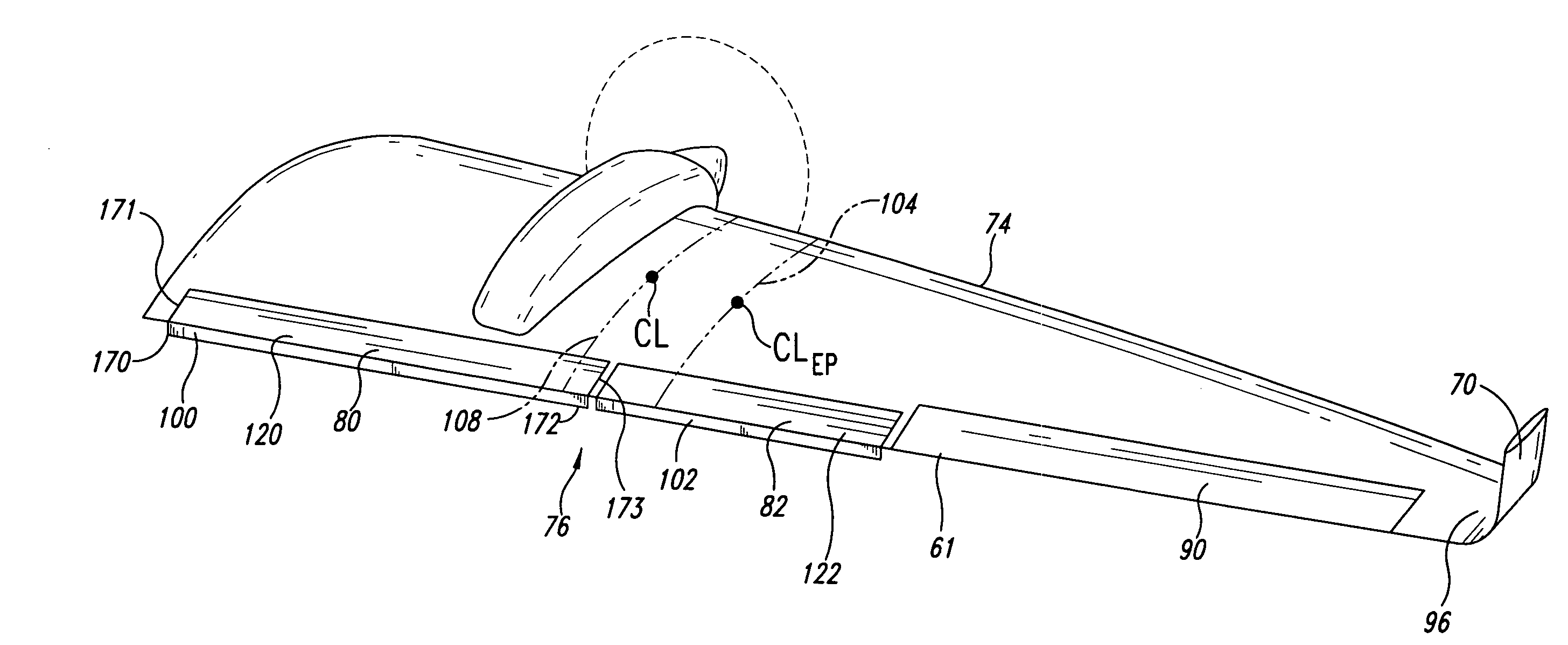
[0052]The headings provided herein are for convenience only and do not interpret the scope or meaning of the claimed invention. The following description relates to lift-generating elements of an aircraft. The lift-generating elements, such as wings, can have at least one fixed gurney flap for altering the pressure distribution along the lift-generating element. These gurney flaps can be positioned at a trailing edge region of the lift-generating elemen...


PUM

PropertyMeasurementUnit
Forceaaaaaaaaaa
Pressureaaaaaaaaaa
Angleaaaaaaaaaa

Abstract

An aircraft can include a wing with a leading edge and a trailing edge. The wing has a main body and movable control surfaces coupled to the main body. The wing generates lifting forces when the aircraft is in flight. The movable control surfaces can be used to control the generated lifting forces. A spanwise flow inhibitor extends from the outer wingtip of the wing. At least one gurney flap extends generally downwardly from at least a portion of the trailing edge of the wing. The flap at least partially counteracts a change in center of lift attributable to the spanwise flow inhibitor.

Description

BACKGROUND OF THE INVENTION[0001]1. Field of the Invention[0002]The present disclosure in some embodiments generally relates to aircraft, and more specifically to aircraft with at least one gurney flap.[0003]2. Description of the Related Art[0004]Aircraft, such as airplanes, often have wingtip fences, commonly referred to as winglets. The wingtip fences typically extend generally vertically from the wingtips of the aircraft. These wingtip fences may increase the effective aspect ratio of the wing. Wingtip fences may reduce induced drag associated with wingtip vortices to improve fuel efficiency, increase cruising speed, improving handling characteristics, and provide a modern appearance often desirable for aircraft.[0005]Wingtip fences typically move the center of lift outwardly towards the wingtip, thus increasing wing bending moments during flight. This increased bending moment may induce fatigue in the wing structure or wing box, and, consequently, requires increased frequency of...

Claims


Application Information

Patent Timeline
IPC IPC(8): B64C3/58B23P11/00
CPCB64C3/58B64C9/18Y10T29/49826Y02T50/164Y02T50/32B64C23/065B64C23/069Y02T50/10Y02T50/30
Inventor DESROCHE, ROBERT J.
Owner DESROCHE ROBERT J
Why Eureka
Try Eureka