Mountable wing tip device for mounting on a rotor blade of a wind turbine arrangement

a technology of wind turbine and rotor blade, which is applied in the direction of wind turbines, engine components, wind energy generation, etc., can solve the problems of aerodynamic short circuit between a pressure side and a suction side loss of blade tip region, and reduced lift-to-drag efficiency of the rotor blade, so as to improve the safety of operation and simplify the installation of the wing tip device. , the effect of increasing production costs

Inactive Publication Date: 2019-09-17
YOUWINENERGY
View PDF13 Cites 1 Cited by
  • Summary
  • Abstract
  • Description
  • Claims
  • Application Information

AI Technical Summary

Benefits of technology

[0013]The concept underlying this device is completely novel and provides various advantageous effects. In particular, according to the basic concept of the present subject matter, the present invention provides a rotor blade which can benefit from the drag reduction afforded by the wing tip device whilst not suffering to great on increase in bending moment in the rotor blade, particularly at the root of the rotor blade at which the blade is connected to a hub of a wind turbine. Preferably the bending moment in the rotor blade, in particular at the hub, during use is, in fact, reduced by the presence of the wing tip device. Further, an aerodynamic short-circuit between a pressure and a suction side of the rotor blade can be prevented by using the concept of the inventive device as due to the present subject matter the losses that occur due to the formation of the vortices at the blade tip can be reduced. Thus, a laminar flow of wind across the rotor blade can be provided, thereby reducing drag that is caused due to short circuit between the suction side and the pressure side of the rotor blade.
[0014]According to an aspect of the present subject matter, a mountable wing tip device is simplified and easy to use, wherein the operational safety is also enhanced. Moreover, a special shaping of the end of a rotor blade which increases production costs is not required as the mountable wing tip device is mountable before installing the rotor blade to a hub of a wind turbine. Further, it is also possible to install the mountable wing tip device after a rotor blade is mounted to a hub. Therefore, according to the basic concept of the present subject matter, the mountable wing tip device has the function of reducing drag and friction of a rotor blade, and also, has the function of reducing costs with regard to mounting and producing a rotor blade with a wing tip device. Also the damages can be avoided as the wing tip device and the rotor blade can be separately transported to the construction side. Further, the mountable wing tip device and the rotor blade can be transported in separate containers in a safe manner thereby minimizing the likelihood that the components will be damaged during transportation. In one implementation, the blade portion can be transported affixed to the rotor blades, onto which the wing tip device can be mounted at the time of assembly. At the construction site, the rotor blade and the wing tip device are connected. Accordingly, the wing tip device of the present subject matter can be easily installed at the rotor blade at the construction site. Further, in case of any damage to the tip portion, the entire rotor blade may not be required to be replaced and just the wing tip device may be changed. This may help in saving time and effort.
[0015]According to an embodiment of the present subject matter, the forward extremity and the at least two rearward extremities are arranged in a triangle.
[0016]Preferably the triangle comprises either sides which all have the same lengths (equilateral triangle) and in which all angles measuring 60 degree or an isosceles triangle having two sides which are equal in length. An isosceles triangle also has two angles of the same measure, namely the angles opposite of the two sides of the same length which are preferably defined by the forward extremity and one rearward extremity. Such a described form is similar to a so called sweep back of a plane's wing which is optimized for airflow when moving.
[0017]According to an embodiment of the present subject matter, the leading edge region comprises a V-shape. Thus, the leading edge region extending between the forward extremity and the at least two rearward extremities comprises a shape which is similar to a triangle. In comparison to the arrangement mentioned before it is possible that the length between one rearward extremity and the forward extremity differs from the length of the forward extremity and another rearward extremity.
[0018]According to an embodiment of the present subject matter, the leading edge region comprises an arced tip portion at the forward extremity. Due to the arced design the aerodynamicity of the mountable wing tip device can be enhanced. Also, the flow conditions at the forward extremity are optimized with regard to friction and drag.

Problems solved by technology

One of the losses which are present in the blade tip region occurs primarily due to the axial direction which the airflow assumes as it flows over the rotor blade.
Due to such non-regular airflow along the blade tip region, aerodynamic losses are introduced which in turn reduce the lift-to-drag efficiency of the rotor blade.
However, despite the curved tip of the rotor blades, an aerodynamic short-circuit between a pressure side and a suction side of the rotor blade might occur.
Such designs however do not address the losses that occur due to the formation of the vortices.
In cases where the blade tip is part of the rotor blades, it is very likely that the blade tips may get damaged during transportation.
Also, if the blade tips suffer damage in the course of their operation, or due to natural occurrences such as lightening, the entire rotor blade has to be replaced.
This further is likely to increase the operational costs associated with the wind turbine.
In addition, it may be inconvenient and time-consuming to perform any checks on the blade tips, once the wind turbine is operational.
Further, since the blade tips typically extend either towards the suction side or the pressure side of the rotor blade, this may cause imbalance when the wind turbine is in operation, thereby causing vibrations in the wind turbine.
Such a fast installation saves costs and allows replacing the wing tip device after damage.

Method used


Image

  • Mountable wing tip device for mounting on a rotor blade of a wind turbine arrangement
  • Mountable wing tip device for mounting on a rotor blade of a wind turbine arrangement
  • Mountable wing tip device for mounting on a rotor blade of a wind turbine arrangement

Examples


embodiment

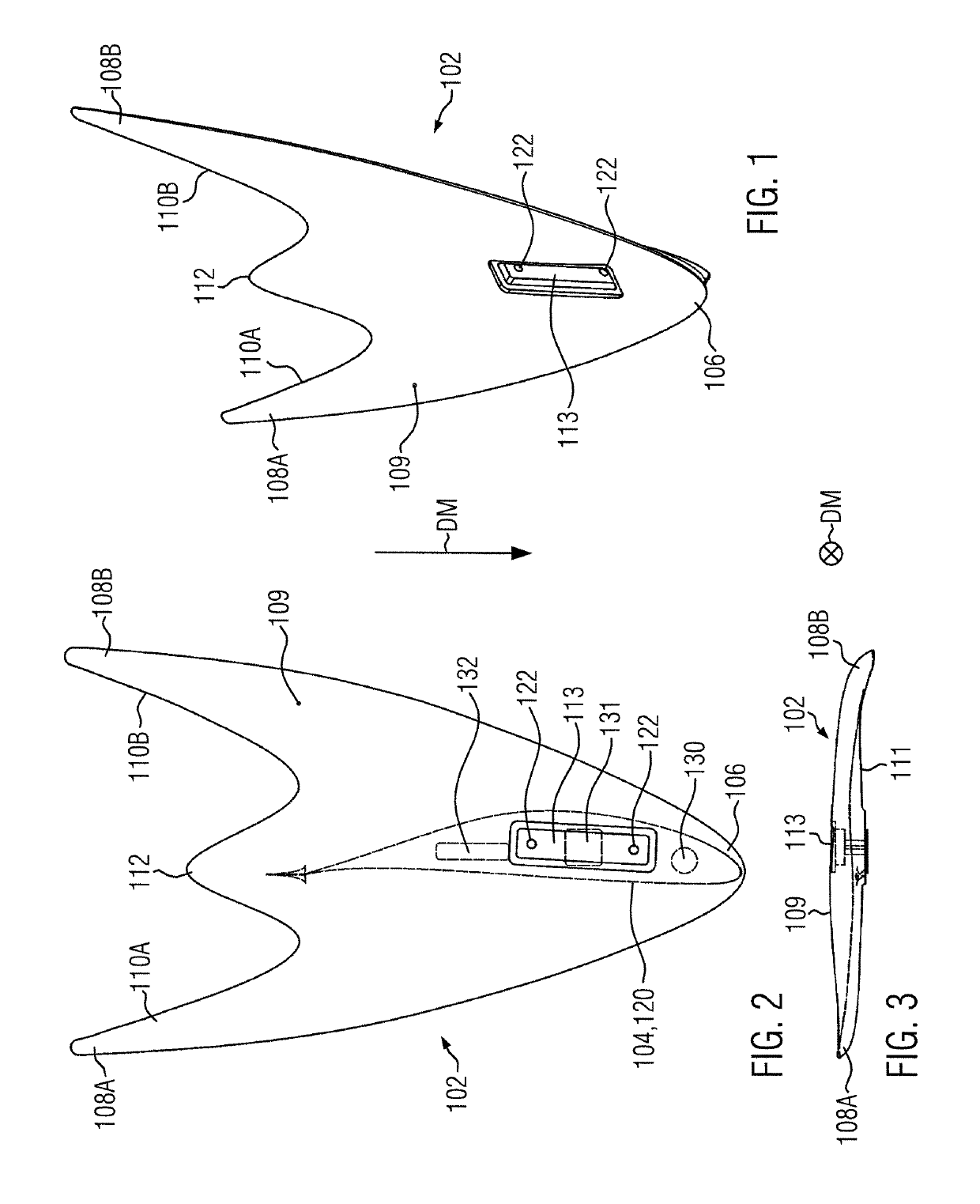
[0057]An embodiment of a mountable wing tip device 102 of the present subject matter is shown in FIGS. 1 and 2 in a three-dimensional view and a top-view, respectively.

[0058]The wing tip device 102 comprises a forward extremity 106 and three rearward extremities: including a first rearward extremity 108A, a second rearward extremity 108B and a third rearward extremity 112. The forward extremity 106 and two of the rearward extremities 108A and 108B are triangularly arranged. Between the two rearward extremities, in particular in the middle of the first and second rearward extremities 108A and 108B, the third rearward extremity 112 is positioned.

[0059]The forward extremity 106 and two of the rearward extremities 108A and 108B are arranged in a triangle which means that the distance between the forward extremity 106 and the rearward extremities 108A, B is similar. However, the distance between the third rearward extremity 112 and the forward extremity 106 comprises a shorter length tha...


PUM


Abstract

A mountable wing tip device (102) for mounting on a rotor blade of a wind turbine is disclosed which comprises a forward extremity (106) and at least two rearward extremities (108A, 108B, 112), wherein the forward extremity (106) and the at least two rearward extremities (108A, 108B, 112) are triangularly arranged, a leading edge region extending between the forward extremity (106) and the at least two rearward extremities (108A, 108B, 112), and a trailing edge region extending between the rearward extremities (108A, 108B, 112), a root region (113) at which the wing tip device (102) is mountable on an end of the rotor blade, wherein the root region (113) is positioned between the leading edge region and the trailing edge region.

Description

CROSS REFERENCE TO RELATED APPLICATION[0001]This application is a 35 U.S.C. 371 National Phase Entry Application from PCT / EP2014 / 064337, filed Jul. 4, 2014, which claims the benefit of European Patent Application No. 13175405.3 filed on Jul. 5, 2015, the disclosures of which are incorporated by reference in their entirety.BACKGROUND OF THE DESCRIPTION[0002]The present subject matter relates to a mountable wing tip device, a blade tip assembly and a wind turbine arrangement.[0003]In a commonly known wind turbine assembly, a rotor blade of a rotor component converts wind energy to low speed rotational energy. Such a rotor blade is connected to a generator positioned in a hub of the wind turbine assembly, wherein the hub is arranged in order to drive the generator while the rotor blade converts wind energy. Opposite to the end of the rotor blade arranged at the hub, the rotor blade comprises a free end which oscillates due to the mixture of the air flow from the pressure and suction si...

Claims


Application Information

Patent Timeline
Patent Type & Authority Patents(United States)
IPC IPC(8): F03D1/06F03D9/25
CPCF03D1/0675F03D1/0658F03D9/25F03D1/0641F03D1/0633Y02E10/721F05B2250/11F05B2240/30F05B2240/302F05B2240/307Y02E10/72
Inventor ROHDEN, ROLF
Owner YOUWINENERGY
Why Eureka
Try Eureka