Electrical connector having high density contacts for miniaturization

a technology of high density contacts and electric connectors, applied in the direction of coupling device details, coupling device connections, printed circuits, etc., can solve the problems of electrical magnetic interference between adjacent contacts, and achieve the effect of high quality signal

Inactive Publication Date: 2011-08-02
HON HAI PRECISION IND CO LTD
View PDF7 Cites 6 Cited by
  • Summary
  • Abstract
  • Description
  • Claims
  • Application Information

AI Technical Summary

Benefits of technology

[0008]An object of the present invention is to provide a miniaturize electrical connector having a plurality of high density contacts, but being able to transmit a high quality signal.

Problems solved by technology

On the contrary, the interval between the two adjacent contacts is required to be smaller and smaller if the original pitch is decreased to keep the original size of electrical connector, so it would generate electronic magnetic interference between adjacent contacts.

Method used


Image

  • Electrical connector having high density contacts for miniaturization
  • Electrical connector having high density contacts for miniaturization
  • Electrical connector having high density contacts for miniaturization

Examples


Embodiment Construction

[0020]Reference will now be made to the drawing figures to describe the preferred embodiment of the present invention in detail.

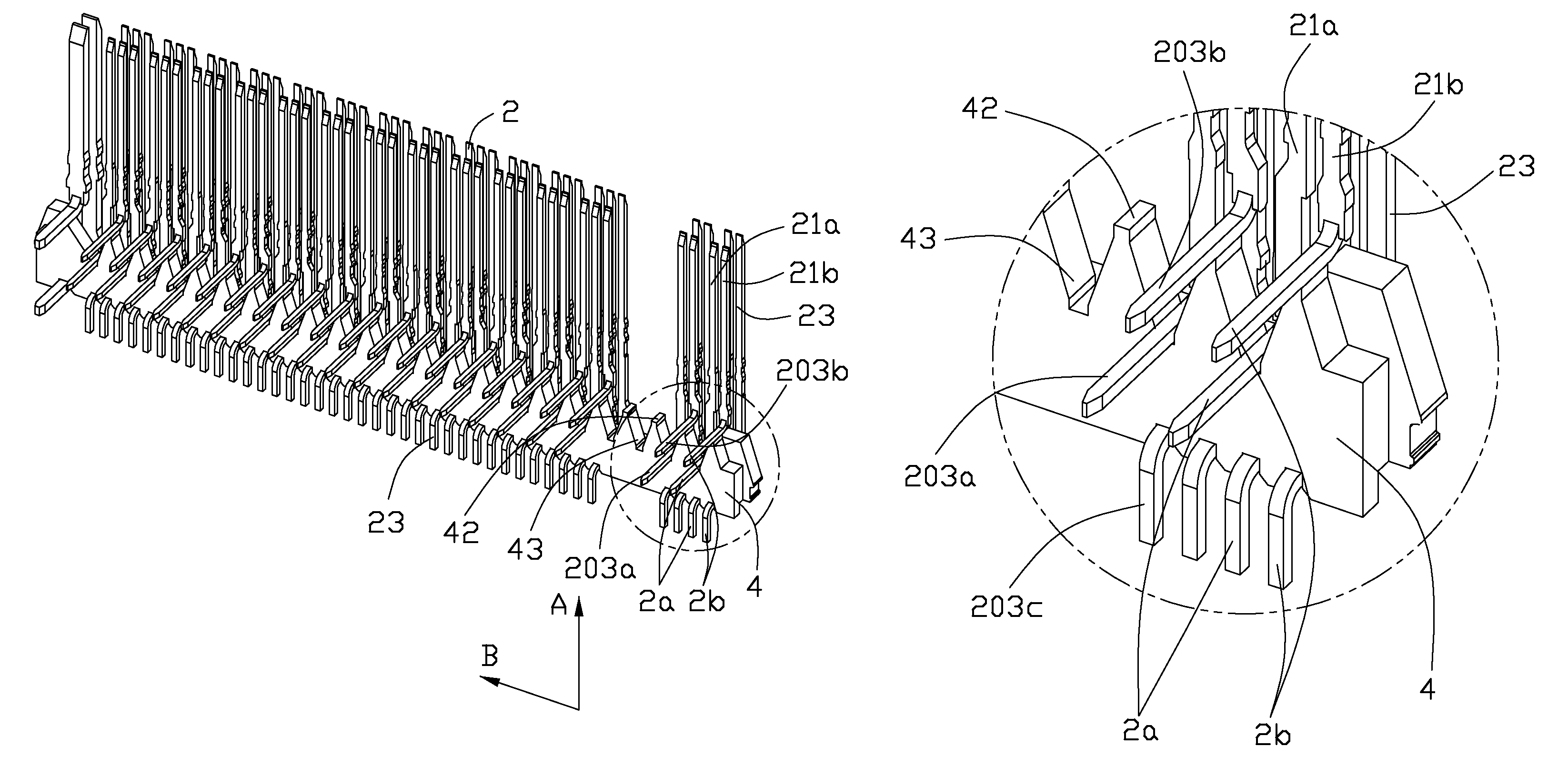
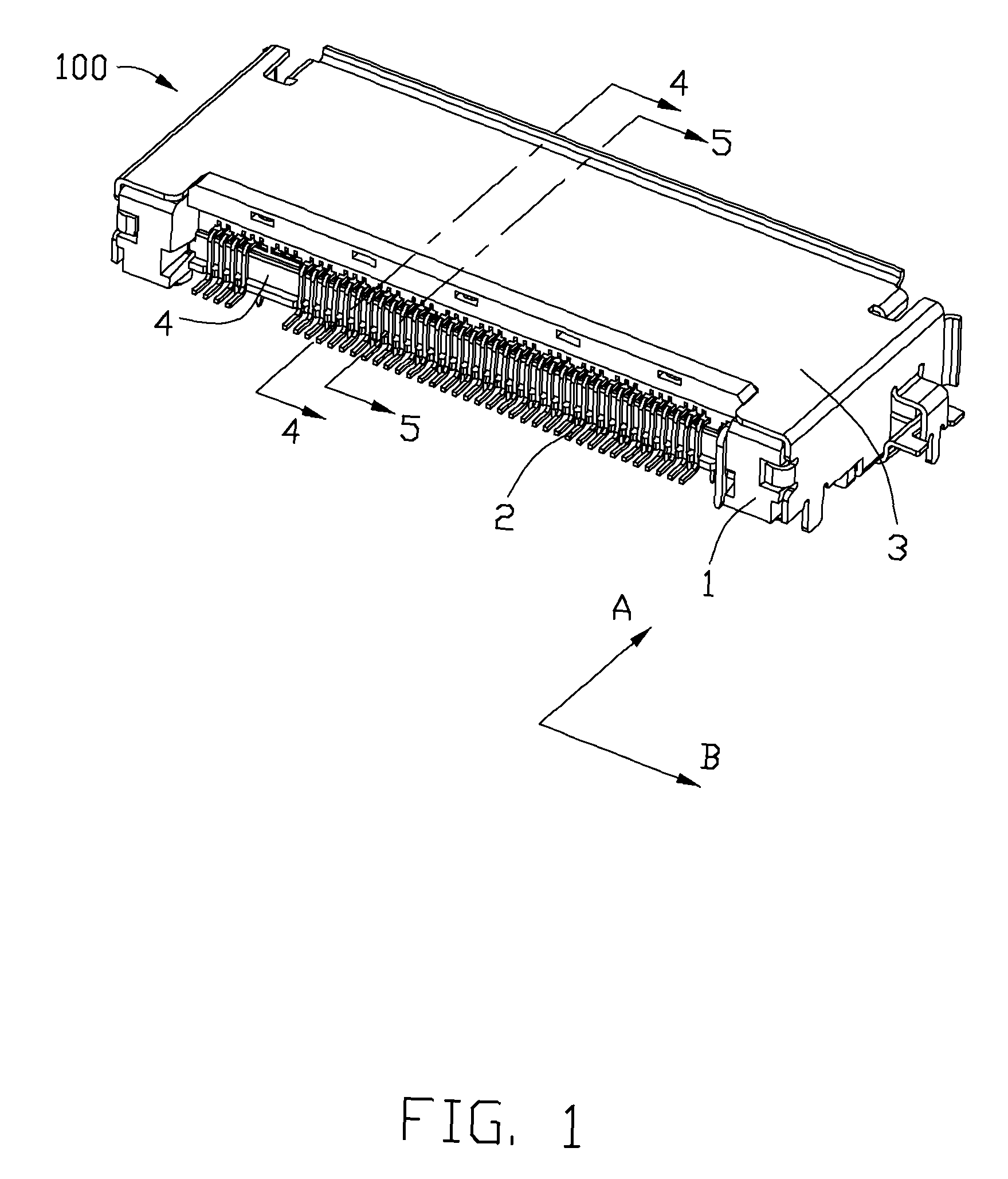
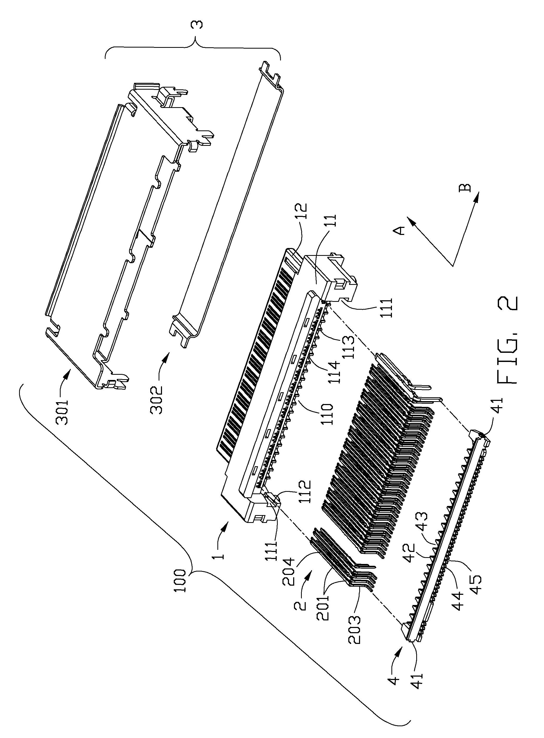
[0021]Referring to FIGS. 1 and 2, an electrical connector 100 in accordance with the present invention includes an insulative housing 1 with a rear portion 11 regarded as a base portion and a front portion 12 regarded as an engaging portion along a first direction, i.e. direction A, a plurality of contacts 2 received in the insulative housing and arranged along a second direction, i.e. direction B, a metallic shell 3 and a spacer 4 assembled on the base portion 11 of the insulative housing 1. The metallic shell 3 includes a top shell 301 and a bottom shell 302 thereby surrounding and covering on the housing 10 for providing a perfect shielding with a simple structure.

[0022]Referring to FIGS. 2, 3 and 4, the engaging portion 12 of the insulative housing 1 is a tongue shape configuration and surrounded by the shell 3 thereby forming a mating space 101 for rec...


PUM


Abstract

An electrical connector includes an insulative housing (1) with a rear portion (11) and a front portion (12) along a first direction (A), a spacer (4) assembled on the rear portion (11) which has a plurality of first wedged positioning sections (42, 43) in an inner side thereof and arranged along a second direction (B) and a plurality of contacts (2) received in the insulative housing and comprising a soldering portion (203) extending out of the insulative housing. The spacer (4) includes a plurality of positioning grooves (45) in an external side thereof for receiving and positioning the soldering portions (203c) of one part contacts (23) located at an upper side of the front portion (12). The soldering portions (203a, 203b) of the other contacts (21a, 21b) are sandwiched between the spacer (4) and the rear portion (11) thereby forms a waved configuration.

Description

[0001]This application is related to so and so U.S. patent application Ser. No. 12 / 755,383, filed Apr. 6, 2010, entitled “LOW PROFILE CONNECTOR WITH COMBO SOLDER TAILS”, and which is assigned to the common assignee, and is incorporated herewith for reference.BACKGROUND OF THE INVENTION[0002]1. Field of the Invention[0003]The present invention relates to an electrical connector having a plurality of high density contacts for miniaturization.[0004]2. Description of the Related Art[0005]U.S. Pat. No. 7,537,465 issued to Mao et. al on May 26, 2009, discloses an electrical connector including an insulative housing, a plurality of contact units arranged in the insulative housing along a horizontal direction, a shielding shell covering on the insulative housing and a spacer assembled with the insulative housing. The insulating housing defines a front end portion and a rear end portion having a first wedged positioning section. The contact includes a tail portion extending out of the rear e...

Claims


Application Information

Patent Timeline
Patent Type & Authority Patents(United States)
IPC IPC(8): H01R12/00
CPCH01R12/724
Inventor MAO, YU-HUAFANG, ZHI-HONG
Owner HON HAI PRECISION IND CO LTD
Why Eureka
Try Eureka