Method of making a cardiac valve

a heart valve and leaflet technology, applied in the field of flexible leaflet heart valves, can solve the problems that many valves constructed using materials with apparently suitable hydrodynamic properties nevertheless fail during use, and the problem of artificial valves still exist, so as to reduce stress and increase the life of synthetic leaflets.

Active Publication Date: 2011-08-02
AORTECH INT
View PDF34 Cites 25 Cited by
  • Summary
  • Abstract
  • Description
  • Claims
  • Application Information

AI Technical Summary

Benefits of technology

[0038]Preferably the frame is a collapsible stent. This may be advantageous as a collapsible stent may be delivered to a patient by percutaneous delivery. In a preferred embodiment of the valve wherein the frame is a collapsible stent, the collapsible stent may be moved from a collapsed to an erect position using an inflatable balloon when the stent is suitably located in the patient.
[0159]This is advantageous as it enables the effect of trimming the leaflet to particular shapes, for example parabolic, to be determined.

Problems solved by technology

However, although improvements have been made to cardiac valves over recent years, problems still exist with artificial valves.
Although several materials have suitable hydrodynamic properties, many valves constructed using materials with apparently suitable hydrodynamic properties nevertheless fail during use, due to fatigue caused by the repeated stresses of cycling from a closed to an open position.

Method used


Image

  • Method of making a cardiac valve
  • Method of making a cardiac valve
  • Method of making a cardiac valve

Examples


Embodiment Construction

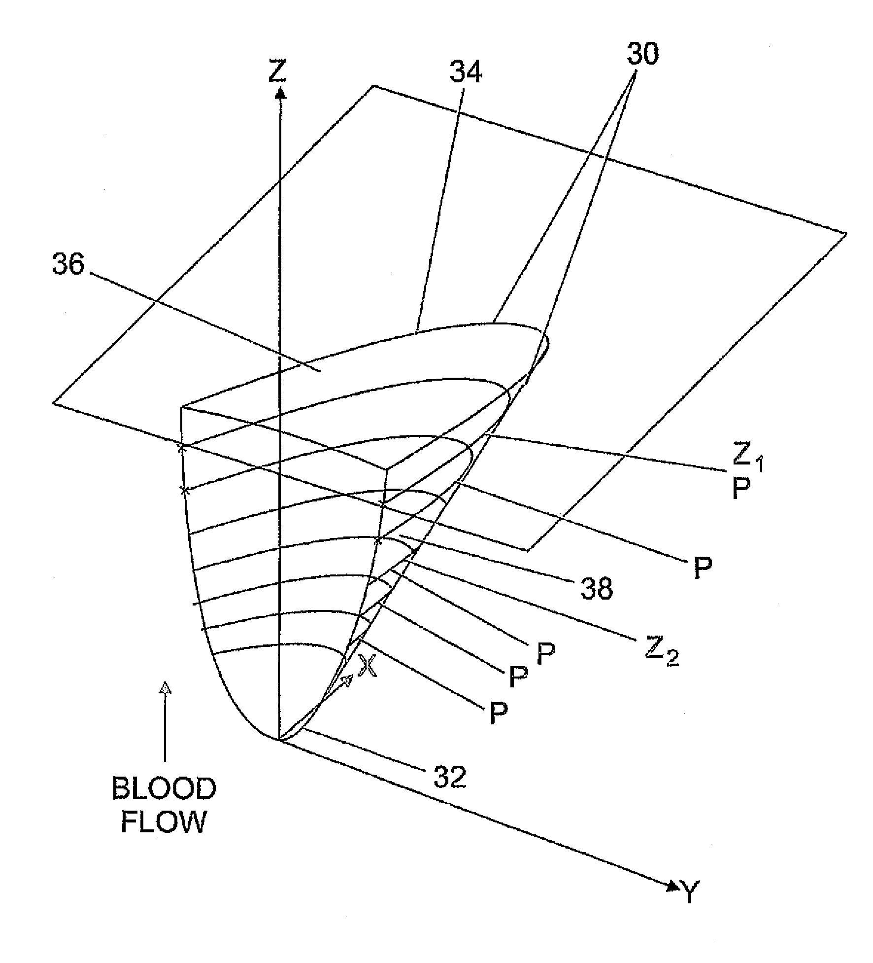
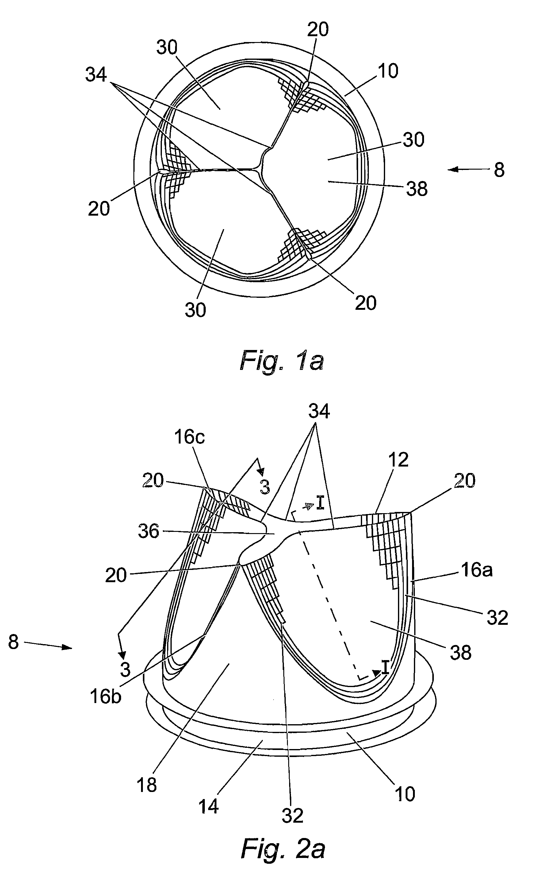
[0199]As previously discussed, a number of designs have been suggested for use in cardiac heart valves to ensure that the heart valves have sufficient leaflet material such that the valve is capable of opening as wide as possible to the maximum orifice of the valve, and that such opening requires as little energy as possible and further that regurgitation of blood through the valve is minimised.

[0200]In order to minimise the regurgitation of blood it has been suggested that the free edge of the valve is spherical in geometry to ensure that the free leaflet edges are able to come together and seal against one another.

[0201]U.S. Pat. No. 5,500,016 discloses a leaflet defined by the equation:

z2+y2=2RL(x−g)−α(x−g)2

to describe the geometry of the leaflets. As Z, defines the shape of the leaflet in the blood flow axis and as Z is defined as z2 then a leaflet defined by the above would have a spherical geometry in the axis parallel to blood flow. International Patent Application WO 98 / 324...


PUM

PropertyMeasurementUnit
diameteraaaaaaaaaa
lengthaaaaaaaaaa
heightaaaaaaaaaa

Abstract

There is provided an artificial cardiac or heart valve, more particularly a flexible leaflet heart valve used to replace natural aortic or pulmonary valves of the heart in which the leaflet geometry is defined by a parabolic function and a method of manufacturing said artificial cardiac valves. In addition, there is provided leaflets which have geometry defined by a parabolic function.

Description

RELATED APPLICATIONS[0001]This application is a divisional of U.S. application Ser. No. 10 / 524,612 filed May 15, 2006, which is a U.S. National Phase of International Application No. PCT / GB2004 / 001244, filed Mar. 22, 2004, which claims priority to GB 0306472.2, filed Mar. 20, 2003 and GB 0319321.6, filed Aug. 16, 2003, the contents of all of which are hereby incorporated by reference in their entirety.DESCRIPTION OF THE RELATED ART[0002]The present invention relates to artificial cardiac or heart valves, more particularly to flexible leaflet heart valves which are used to replace natural aortic or pulmonary valves of the heart.[0003]Ideally artificial heart valves should work in a similar fashion to natural heart valves in that when blood flows in a particular direction the valve adopts an open position to permit blood flow through it, whereas when blood tries to flow in the opposite direction the valve adopts a closed position preventing the flow of blood in the reverse direction t...

Claims


Application Information

Patent Timeline
Patent Type & Authority Patents(United States)
IPC IPC(8): B29C41/00A61F2/24
CPCA61F2/2412A61F2/2415
Inventor BEITH, JASON GORDON
Owner AORTECH INT
Why Eureka
Try Eureka