
A Wave Direction Inversion Method for Shipborne Coherent Microwave Radar

A microwave radar, wave direction technology, applied in radio wave measurement systems, instruments, etc., to achieve the effect of a large scope of application and application prospects

Active Publication Date: 2022-04-15
WUHAN UNIV
View PDF8 Cites 0 Cited by
  • Summary
  • Abstract
  • Description
  • Claims
  • Application Information

AI Technical Summary

Problems solved by technology

With the movement of the ship, the irradiation area of ​​the ship-borne coherent microwave radar continues to change, so the above method is not suitable for the ship-borne coherent microwave radar

Method used


Image

  • A Wave Direction Inversion Method for Shipborne Coherent Microwave Radar
  • A Wave Direction Inversion Method for Shipborne Coherent Microwave Radar
  • A Wave Direction Inversion Method for Shipborne Coherent Microwave Radar

Examples


Embodiment Construction

[0100] In order to make the object, technical solution and advantages of the present invention more clear, the present invention will be described in detail below in combination with the accompanying drawings and implementation examples. It should be understood that the specific implementation cases described here are only used to explain the present invention, and are not intended to limit the invention.

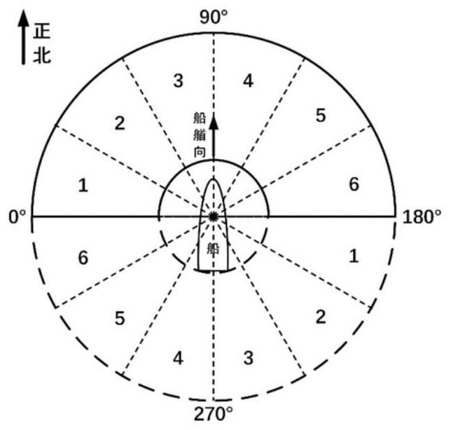
[0101] Combining the characteristics of the ship-borne coherent microwave radar, the invention proposes a wave direction inversion method for the ship-borne coherent microwave radar based on space sampling and the characteristics of the left and right bandwidth boundary frequencies of the range Doppler spectrum. The invention realizes the inversion of the wave direction of the sea waves on the premise that there is no special restriction on the motion of the ship.

[0102] The method provided by the invention can use computer software to realize the process. The present in...


PUM


Abstract

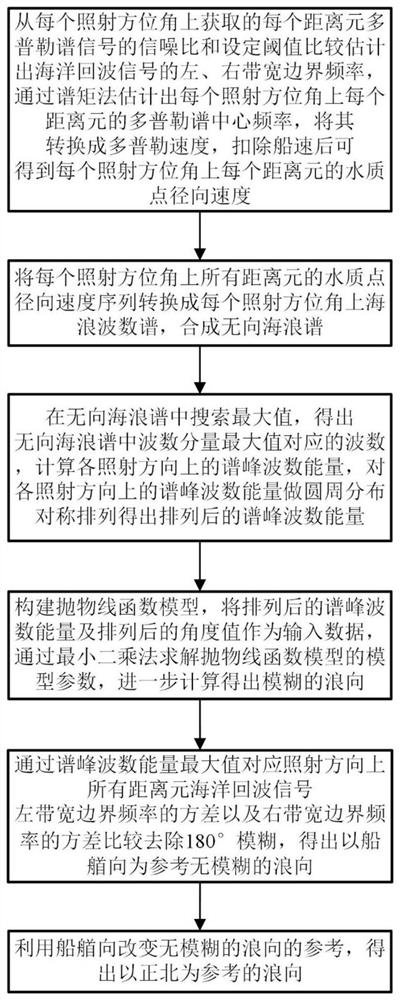
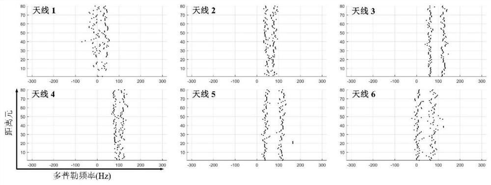
The invention proposes a wave direction inversion method for ship-borne coherent microwave radar. This method first estimates the left and right bandwidth boundary frequencies and center frequency of the ocean echo signal from the range Doppler spectrum echoes obtained from multiple irradiation directions of the radar, and then converts the center frequency into velocity and deducts the ship speed component to obtain the water quality. point speed. Then the water particle velocity measured in each direction is converted into a wave number spectrum to synthesize an undirected ocean wave spectrum. Then, the wave value corresponding to the peak is obtained from the undirected wave spectrum by searching for the maximum value, and the wave number energy of the peak in each direction is arranged symmetrically in a circular distribution, and then the fuzzy wave direction is obtained by constructing a parabolic function model. Then, the variance of the left and right bandwidth boundary frequencies corresponding to the maximum irradiation direction of the spectral peak wave number energy is used to eliminate the 180° ambiguity. Finally, combined with the heading of the ship, the wave direction with true north as the reference is obtained. The invention enables the ship-borne coherent microwave radar to have the capability of navigating and monitoring the direction of sea waves.

Description

technical field [0001] The invention belongs to the field of radar signal processing, in particular to a wave direction inversion method for ship-borne coherent microwave radar. Background technique [0002] Ocean observation is the basic means of understanding the ocean and the basis for marine economic development, environmental protection and rights protection. Waves are the most common phenomenon in the ocean. Wave direction is an important parameter to quantitatively describe the physical characteristics of ocean waves. Microwave radar is a remote sensing monitoring method widely used in ocean wave parameter measurement. It has the characteristics of wide measurement range, high temporal and spatial resolution, and convenient maintenance and management. Coherent microwave radar is based on the Doppler principle, which can continuously measure the movement speed of waves and water particles in all directions. Combined with the ocean wave theory, the wave direction ca...

Claims


Application Information

Patent Timeline
Patent Type & Authority Patents(China)
IPC IPC(8): G01S7/41
CPCG01S7/415
Inventor 陈泽宗张春阳赵晨陈曦
Owner WUHAN UNIV
Learn More