System and method for evaluating equipment rack cooling performance

a technology for equipment racks and cooling performance, applied in the direction of heat measurement, electrical apparatus casings/cabinets/drawers, instruments, etc., can solve the problems of putting strain on the cooling and power systems of facilities, unable to analyze the cooling capacity at the facility level, and other hot spots to arise, so as to achieve the effect of optimizing the layou

Active Publication Date: 2011-08-02
SCHNEIDER ELECTRIC IT CORP
View PDF61 Cites 76 Cited by
  • Summary
  • Abstract
  • Description
  • Claims
  • Application Information

AI Technical Summary

Benefits of technology

[0181]One advantage of the use of NN in embodiments of the present invention lies in its ability to establish non-linear relationships between cluster-layout details (input vector) and resulting rack capture indices (output vector). The former includes the physical arrangement of racks and coolers, rack power and airflow, and cooler airflow. In at least some embodiments, thousands of hypothetical but realistic cluster layouts are designed, and then the hot-aisle CI values are computed using Computational Fluid Dynamics (CFD) for each layout. Finally, the NN model is trained to “learn” the relationship between the input and output vectors. While the training data may be produced by a traditional CFD analysis, considerable time savings can be achieved by using the PDA-CFD techniques discussed above. Given sufficient training data, the Neural Networks can be applied to virtually any data center cooling application. However, as an example, the prediction of CI values for a 14 ft (4.27 m) long cluster of racks and coolers bounding a hot-aisle as shown in FIG. 11 will now be described. A similar methodology can be adapted to design NN models for other cluster lengths.

Problems solved by technology

In modern data centers and network rooms, the increased density of computing equipment used in these facilities has put strains on the cooling and power systems of the facilities.
However, hot spots in a facility may develop, particularly where high power density equipment is used, and it may not be enough to merely analyze cooling capacity at the facility level.
In any case, these fixes are typically done on a trial and error basis, and while some hot spots may be eliminated, the fixes may cause other hot spots to arise due to a redirection of the cooling air in the facility.
This trial and error approach can lead to unexpected failures of equipment, which is unacceptable in critical data centers.
To avoid such failures, data center managers typically over design facilities and fail to use facilities to their full capacity.

Method used


Image

  • System and method for evaluating equipment rack cooling performance
  • System and method for evaluating equipment rack cooling performance
  • System and method for evaluating equipment rack cooling performance

Examples


Embodiment Construction

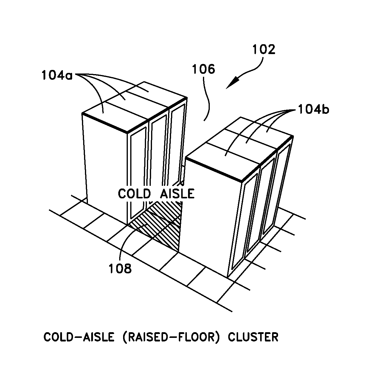
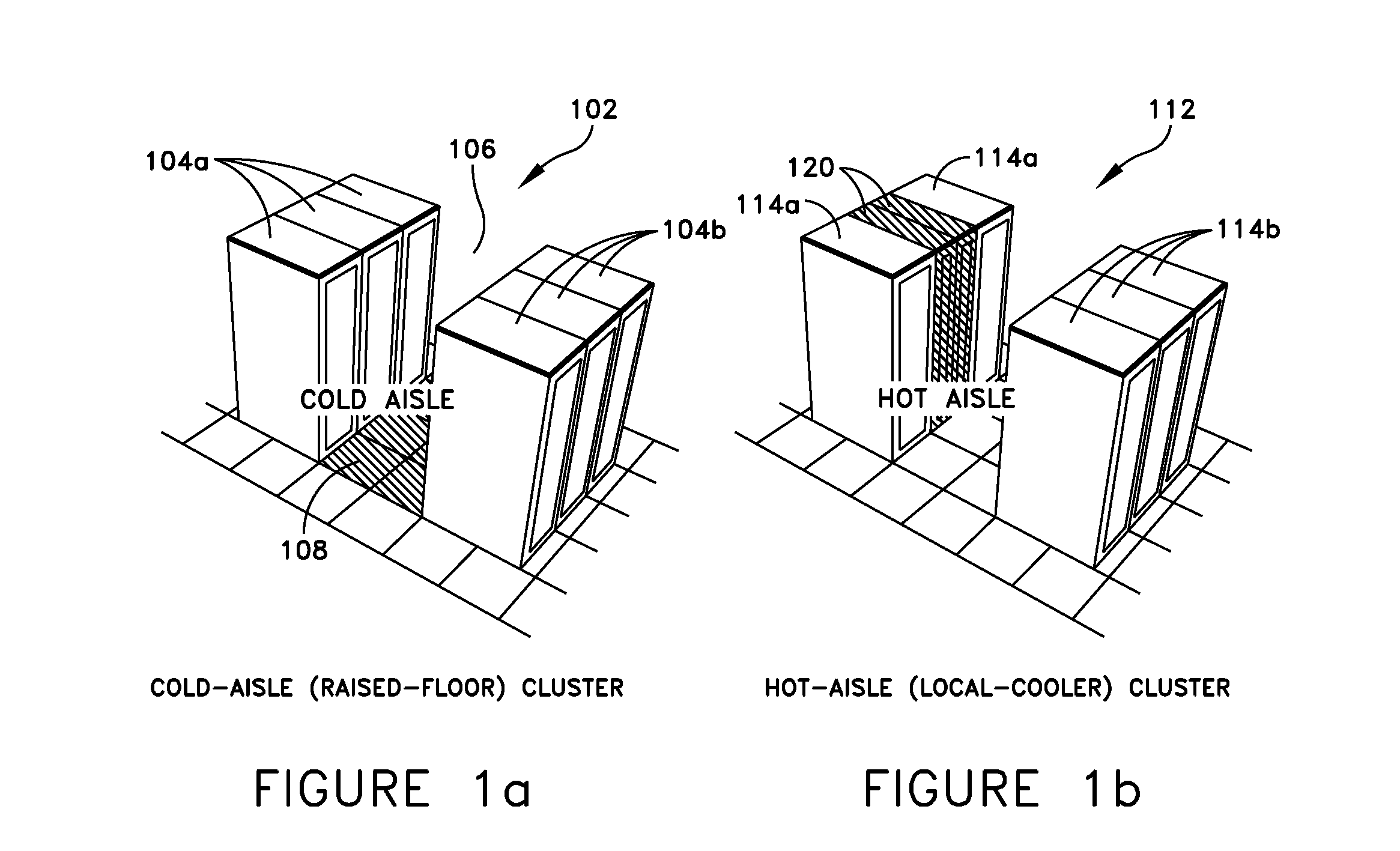
[0040]Embodiments of the invention are not limited to the details of construction and the arrangement of components set forth in the following description or illustrated in the drawings. Embodiments of the invention are capable of being practiced or of being carried out in various ways. Also, the phraseology and terminology used herein is for the purpose of description and should not be regarded as limiting. The use of “including,”“comprising,” or “having,”“containing”, “involving”, and variations thereof herein, is meant to encompass the items listed thereafter and equivalents thereof as well as additional items. Within a data center, racks of electronics equipment are typically arranged in rows with cooling air supplied via a raised floor through perforated floor tiles. Warm air is typically returned to the room environment and ultimately to cooling units located around the perimeter of the room. Another option is to locate cooling units directly within or around the rows of racks...


PUM

PropertyMeasurementUnit
power consumptionaaaaaaaaaa
temperatureaaaaaaaaaa
inlet temperaturesaaaaaaaaaa

Abstract

Aspects of the invention are directed to systems and methods for designing and analyzing data centers. One aspect is directed to a method of determining cooling characteristics of a data center. The method includes receiving data related to a configuration of equipment in the data center, identifying rack clusters in the configuration of equipment, and determining a capture index for at least one equipment rack of at least one rack cluster.

Description

RELATED APPLICATIONS[0001]The present application claims priority under 35 U.S.C. §119(e) to U.S. Provisional Application Ser. No. 60 / 897,076, filed Jan. 24, 2007, entitled SYSTEM AND METHOD FOR EVALUATING EQUIPMENT RACK COOLING PERFORMANCE, and U.S. Provisional Application Ser. No. 60 / 938,034, filed May 15, 2007, entitled METHOD AND SYSTEM FOR MANAGING FACILITY POWER AND COOLING, both of which are hereby incorporated herein by reference.BACKGROUND OF INVENTION[0002]1. Field of Invention[0003]At least one embodiment of the invention relates generally to methods and systems for analyzing and managing facility power and cooling.[0004]2. Discussion of Related Art[0005]Centralized data centers for computer, communications and other electronic equipment have been in use for a number of years, and more recently with the increasing use of the Internet, large scale data centers that provide hosting services for Internet Service Providers (ISPs), Application Service Providers (ASPs) and Inte...

Claims


Application Information

Patent Timeline
Patent Type & Authority Patents(United States)
IPC IPC(8): G06F17/50G01K3/00G01K5/00G01K7/00G01K9/00G01K11/00G01K1/00
CPCH05K7/20836H05K7/20745
Inventor VANGILDER, JAMES W.SHRIVASTAVA, SAURABH K.ZHANG, XUANHANG
Owner SCHNEIDER ELECTRIC IT CORP
Why Eureka
Try Eureka