Reference beam generator and method

a reference beam and generator technology, applied in the direction of reference lines/planes/sectors, angle measurement, instruments, etc., can solve the problems of reducing battery life, limited application of devices, and limited use of stationary reference beams, so as to improve the construction and operation of the generator

Inactive Publication Date: 2011-08-09
SPECTRA PRECISION (USA) LLC
View PDF25 Cites 26 Cited by
  • Summary
  • Abstract
  • Description
  • Claims
  • Application Information

AI Technical Summary

Benefits of technology

[0006]These needs are met by a reference beam generator that includes a first projection turret for projecting a first fan beam of laser light, a second projection turret for projecting a second fan beam of laser light, and a third projection turret for projecting a third fan beam of laser light. The first fan beam of laser light is projected in a first plane, the second fan beam of laser light is projected in a second plane normal to the first plane, and the third fan beam of laser light is projected in a third plane that is normal to both the first plane and the second plane. A turret support supports the first, second, and third projection turrets such that each turret may be pivoted through a complete revolution about an axis that is normal to the plane in which it projects a fan beam of laser light. The turret support includes a first pivot arrangement for supporting the first turret, a second pivot arrangement for supporting the second turret, and a third pivot arrangement for supporting the third turret. Each of the first, second and third pivot arrangements permits an operator to rotate the turret manually and provides sufficient friction that the turret remains in position after it is rotated.
[0007]Each of the first, second, and third projection turrets may comprise a laser diode providing a beam of laser light; a power source for providing power to the laser diode; and a lens for redirecting the beam into a fan shape. The power source in each of the turrets may comprise a battery. Each of the projection turrets may further comprise a turret body housing the laser diode, the power source, and the lens, with each of the projection turrets having a pivot arrangement connecting the turret body to the turret support. The pivot arrangement provides for pivotal movement of the turret about an axis substantially normal to the plane in which the fan beam of laser light is projected from the turret. Bubble vials may be provided on the turret support to facilitate leveling the turret support, so that the fan beams can be projected in vertical or horizontal planes.
[0014]Accordingly, it is an object to provide a reference beam generator in which the construction and operation of the generator are improved.

Problems solved by technology

While useful, such devices have limited application.
Stationary reference beams are of limited use.
Not only does this reduce battery life, but it also raises safety concerns.

Method used


Image

  • Reference beam generator and method
  • Reference beam generator and method
  • Reference beam generator and method

Examples


Embodiment Construction

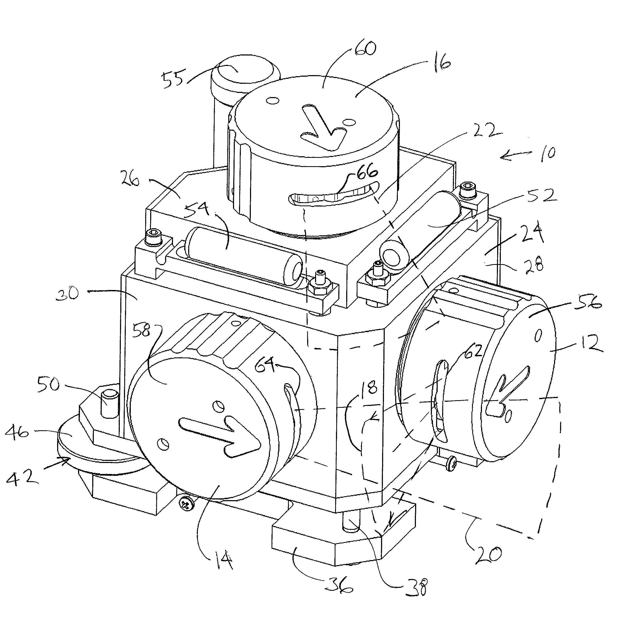
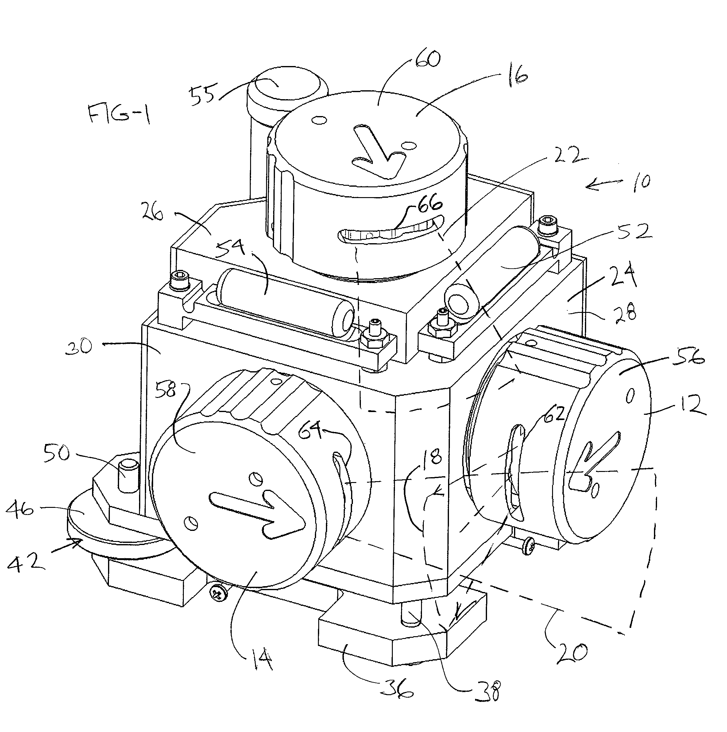
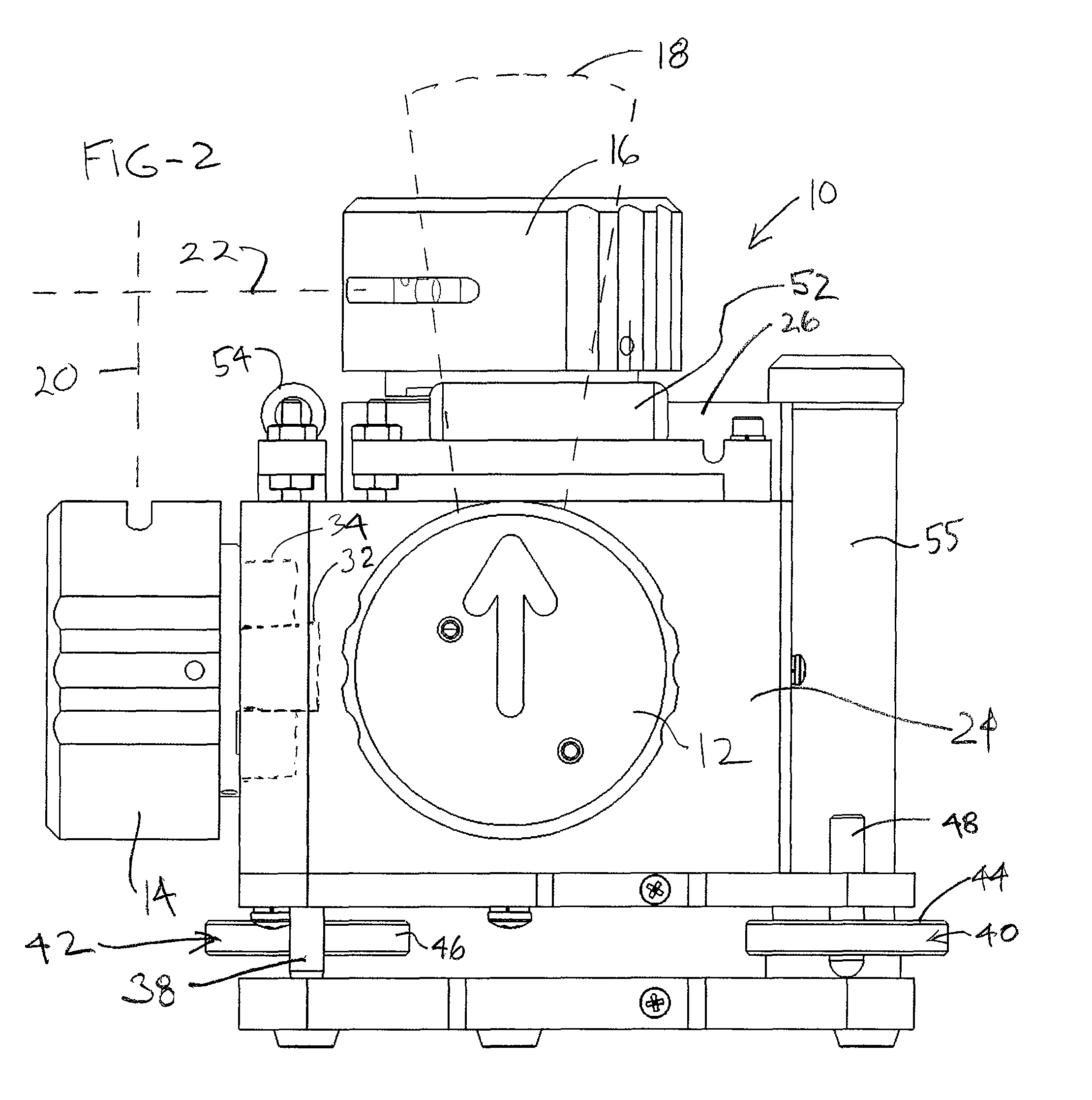
[0021]Reference is made to FIGS. 1 through 4, which illustrate a reference beam generator 10 that includes first, second, and third projection turrets 12, 14, and 16, respectively. The first projection turret 12 projects a first fan beam of laser light 18, shown diagrammatically in dashed lines. The fan beam of laser light 18 is projected in a first plane, depicted in FIG. 1 as a vertical plane. The second projection turret 14 projects a second fan beam of laser light 20. The second fan beam of laser light 20 is projected in a second plane normal to said first plane. This is also shown as a vertical plane. Finally, the third projection turret 16 projects a third fan beam of laser light 22. The third fan beam of laser light 22 is projected in a third plane, shown as a horizontal plane that is normal to both the first plane and to the second plane in which the first fan beam 18 and the second fan beam 20 are positioned, respectively. The fan shaped beams 18, 20 and 22 are depicted, fo...


PUM


Abstract

A reference beam generator has first, second, and third projection turrets for projecting first, second, and third fan beams of laser light, respectively. The first, second, and third fan beams of laser light are oriented normal to each other. The turrets may be rotated such that each of said fan beams can each be rotated about an axis that is normal to the plane in which the fan beam is projected. The generator may be used to project a number of reference points and lines on multiple surfaces.

Description

CROSS-REFERENCE TO RELATED APPLICATION[0001]Not applicable.STATEMENT REGARDING FEDERALLY SPONSORED RESEARCH OR DEVELOPMENT[0002]Not applicable.BACKGROUND OF THE INVENTION[0003]This relates to reference beam generators of the type used to project plumb, level, and square reference beams of visible light on walls, ceilings or floors to facilitate spatial positioning at a construction site or elsewhere. Such tools have been used to provide visible reference lines for construction layout of walls, beams, joists, ceilings, laying tiles, hanging shelves and cabinets, and for a many other similar activities.[0004]Prior art reference beam generators have typically produced only one or two reference beams in specific geometric configurations. While useful, such devices have limited application. Additionally, commonly such devices provide stationary reference beams, or rotating beams. Stationary reference beams are of limited use. Devices which produce rotating reference beams, provide the ab...

Claims


Application Information

Patent Timeline
Patent Type & Authority Patents(United States)
IPC IPC(8): G01C15/00G01B11/26
CPCG01C15/004Y10S33/21
Inventor LITVIN, TIMOTHY J.MORRISSEY, KEVIN MARCCURTISS, STEVE
Owner SPECTRA PRECISION (USA) LLC
Why Eureka
Try Eureka