
Shifting claw transmission and shifting method therefor

a transmission and shifting technology, applied in the direction of gearing control, gearing elements, gearing, etc., can solve the problem that the slow-acting electric motor cannot meet the high dynamic requirements, and achieve the effect of facilitating shifting

Inactive Publication Date: 2011-08-09
DAIMLER AG
View PDF14 Cites 5 Cited by
  • Summary
  • Abstract
  • Description
  • Claims
  • Application Information

AI Technical Summary

Benefits of technology

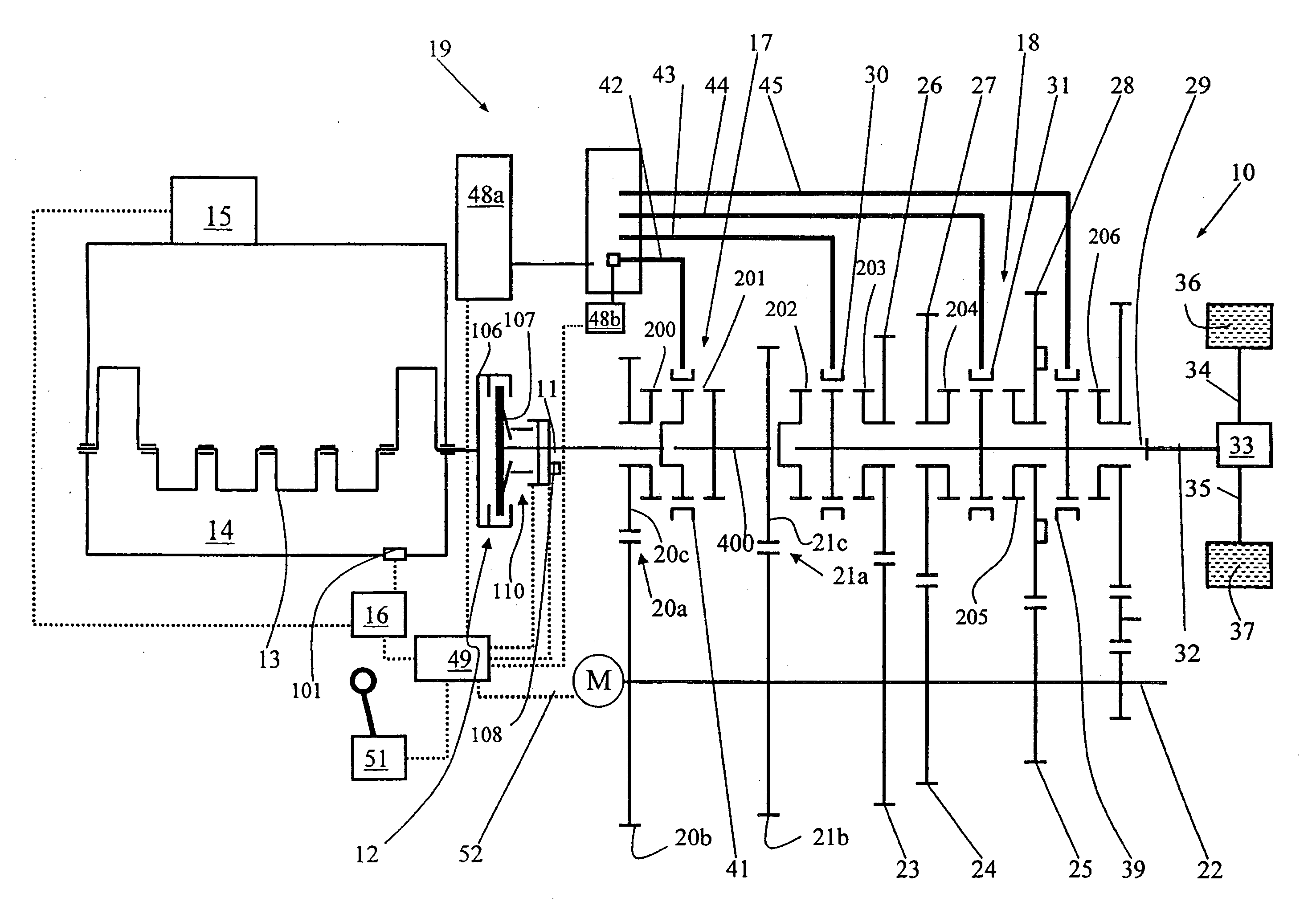
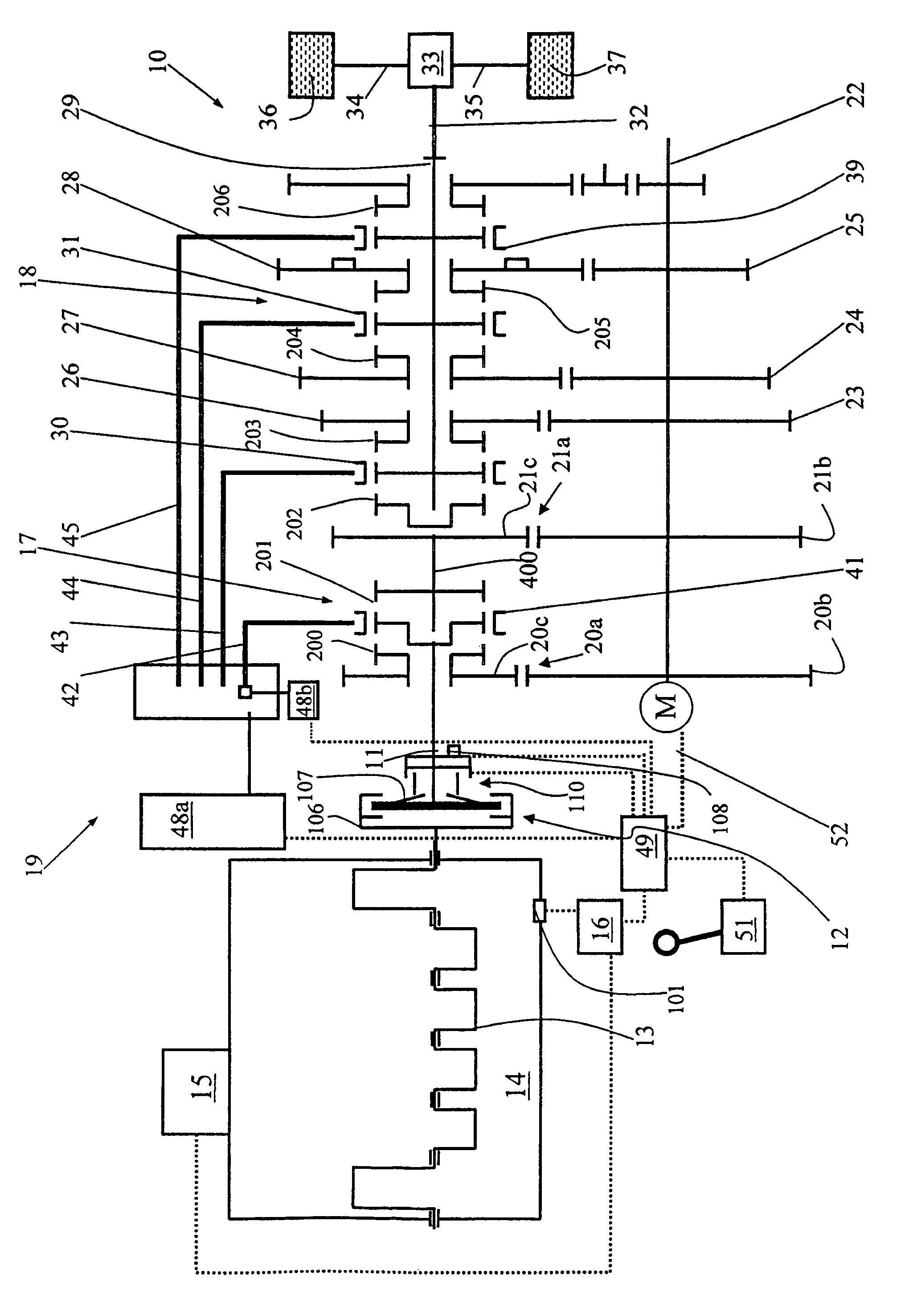
[0011]In a shifting claw transmission for a motor vehicle including a main shaft and a countershaft and an electric motor for rotating the countershaft or being rotated thereby with freely rotatable gear wheels supported on the counter shaft and engageable with the countershaft by claw engagement structures, the speed of the countershaft is adjustable by the electric motor to be close to, but somewhat different from, the speed of the freely rotatable gear wheels to be engaged in order to facilitate shifting but avoid a tooth-on-tooth problem which would inhibit shifting.
[0022]An electric motor has the advantage over hydraulic actuator elements, such as for example a hydraulic transmission multidisk brake, in that its operation is independent of the temperature of the transmission oil. Compared to such a transmission multidisk brake, there are also no churning losses in the transmission oil bath so that the overall efficiency of the shifting claw transmission is improved and the fuel consumption of the vehicle is reduced.
[0024]A clutch can be provided between the countershaft and the electric motor. However, omitting such a clutch provides advantages. For example, given correspondingly small dimensioning of the electric motor, the rotating masses are small compared to the countershaft so that positive and negative accelerations of the countershaft take place very dynamically. Absence of such a clutch means that no additional actuator elements which could entail disadvantageous dynamic effects are present.
[0025]In a particularly advantageous embodiment the rotational speed of the countershaft can be adjusted by means of the electric motor to a certain value, in contrast to providing only for a pure speed increase or decrease control. This provides dynamic advantages, in particular over friction brakes which are not suitable for regulated operation due to their dynamics.
[0026]It is particularly advantageous if a control technology is provided whereby the countershaft can be rotated by means of the electric motor both when the vehicle is stationary and when the vehicle is traveling, in order to avoid a tooth-on-tooth position of the shifting claws.

Problems solved by technology

The problem which is associated with omitting blocking synchronous rings, is that, in rare cases, the shifting tooth or claw arrangements of the shifting claw clutch can be in a tooth-on-tooth position preventing shifting, particularly when the vehicle is not moving.
An electric motor with such capability would have to have such large dimensions that it would be slow-acting.
Such a slow-acting electric motor could not meet the high dynamic requirements which an electric motor has to meet in order to be able to quickly accelerate and / or brake the countershaft for comfortable and rapid gear speed changes.

Method used


Image

  • Shifting claw transmission and shifting method therefor
  • Shifting claw transmission and shifting method therefor

Examples


first embodiment

[0057]In a first embodiment, the signal here may be fed to the electric motor M if the transmission controller 48a senses that the power demand to displace the sliding sleeve by means of the respective switching rod rises above a threshold value. Such a high power demand can specifically allow the conclusion to be drawn that the XY actuator cannot displace the sliding sleeve any further because it is in a tooth-to-tooth position with the shifting tooth arrangement.

second embodiment

[0058]In a second embodiment, the signal of the transmission controller to rotate the countershaft by means of the electric motor M may be provided whenever a gear speed is to be engaged. As a result, the tooth-to-tooth problem cannot occur from the outset.

[0059]The electric motor can be arranged coaxially with respect to the countershaft. In an alternative embodiment, the electric motor can also be coupled to the countershaft by means of a step-down transmission i>1. By means of this step-down transmission it is ensured, on the one hand, that the electric motor can have very small dimensions and nevertheless can make available sufficient torque in order to accelerate the countershaft. On the other hand, the rotational speed of the countershaft with respect to the electric motor is stepped up so that even low rotational speeds of the countershaft induce a relatively high rotational speed and therefore a relatively high voltage at the electric motor. In this way it is also possible t...


PUM


Abstract

In a shifting claw transmission for a motor vehicle including a main shaft and a countershaft and an electric motor for rotating the countershaft or being rotated thereby with freely rotatable gear wheels supported on the counter shaft and engageable with the countershaft by claw engagement structures, the speed of the countershaft is adjustable by the electric motor to be close to, but somewhat different from, the speed of the freely rotatable gear wheels to be engaged in order to facilitate shifting but avoid a tooth-on-tooth problem which would inhibit shifting.

Description

[0001]This is a Continuation-In-Part Application of pending International patent application PCT / EP2006 / 008430 filed Aug. 29, 2006 and claiming the priority of German patent application 10 2005 043 700.1 filed Sep. 14, 2005.BACKGROUND OF THE INVENTION[0002]The present invention relates to a shifting claw transmission including an electric motor, particularly for a motor vehicle, and to a shifting method for shifting a shifting claw transmission of a motor vehicle.[0003]U.S. Pat. No. 5,560,249 discloses a group transmission with claw clutches in which a power synchronizer which comprises an electric motor is used. The electric motor drives a countershaft via an intermediate gearwheel.[0004]In addition, DE 42 020 83 C2, which is of a different generic type, discloses, for a hybrid vehicle, a vehicle transmission which has a frictionally locking synchronization means and an electric machine dynamo. The dynamo electric machine can be operatively connected to a countershaft so that the l...

Claims


Application Information

Patent Timeline
Patent Type & Authority Patents(United States)
IPC IPC(8): F16H59/38F16H3/38
CPCF16H3/126F16H61/0403F16H37/042F16H37/046Y10T74/19284F16H2312/022F16H2061/047Y10T74/1926F16H2061/0422
Inventor KRIEGER, KARL-LUDWIGSAGER, FRANK
Owner DAIMLER AG
Learn More