Method and apparatus for cutting a continuously guided rod into rod-shaped articles of variable length

a technology of continuous conveying and cutting rods, which is applied in the direction of metal working apparatus, tobacco, cigar manufacture, etc., can solve the problems of corresponding displacement of counter supports, and achieve the effect of avoiding breakdown of production and reducing adjustment expenditur

Inactive Publication Date: 2011-08-09
HAUNI MASCHINENBAU AG
View PDF28 Cites 4 Cited by
  • Summary
  • Abstract
  • Description
  • Claims
  • Application Information

AI Technical Summary

Benefits of technology

[0006]It is therefore the object of the present invention to provide an apparatus which enables simplified displacement for cutting articles of variable length. Further, it is the object of the invention to provide a continuous rod-making machine which is easy to adjust. A further object consists in proposing a method for cutting articles of variable length which is simple and easy to handle.
[0007]This object is firstly achieved by an apparatus with the characteristics mentioned hereinbefore by the fact that the displacing devices for the cutting device and the counter-support are coupled together to make a functional connection. As a result, in a surprisingly simple and particularly effective manner an alteration of the length of the articles to be cut is guaranteed. The apparatus of adjustable length according to the invention ensures that the displacement of one component by means of the functional connection leads to automatic simultaneous displacement of the other component. In other words, displacement e.g. of the cutting device inevitably leads to corresponding displacement of the counter-support. Furthermore, the functional connection provides automatic and inevitable adaptation of the displacement of the cutting device on the one hand and of the displacement of the counter-support, on the other hand, this being without any intervention by an operator. Accordingly, inter alia quick and reliable displacement of the whole apparatus is advantageous, the displacement requiring no special technical knowledge or experience. Furthermore, due to the functional connection of the above-mentioned components, release and fixing expenditure is considerably reduced, as the actual displacement has to be made on only one single component.
[0008]Preferably, an adjusting drive is associated with both the counter-support and the cutting device, whereby the adjusting drives are connected to each other by a control system for making the functional connection. As a result, easy adjustment of the cutting device and counter-support is assisted particularly effectively.
[0009]In an advantageous development of the invention, a device for superimposing a displacing movement in addition to the actual driving movement is associated with the counter-support. On the one, the device enables particularly easy and precise displacement of the counter-support depending on the selected article length. On the other hand, the device also ensures adjustment or displacement of the position of the counter-support during operation of the apparatus, so that down-times of the apparatus for the purposes of displacement can be reduced or even completely avoided.
[0012]Moreover, the object is achieved by a method with the steps mentioned hereinbefore by the fact that, to alter the length of the articles to be cut off the rod, only one component is displaced, namely optionally the cutting device or the counter-support, and the other component is automatically displaced in interdependence with the displaced component. As a result, the adjustment expenditure is considerably reduced. Furthermore, coordination of the individual components with each other does not depend on the operator, as automatic displacement of the other component on the basis of the displaced component results in automatic adaptation.
[0013]Preferably, displacement can also take place while the machine is running, so that stopping of the machine can be dispensed with and a breakdown of production can be avoided.

Problems solved by technology

In other words, displacement e.g. of the cutting device inevitably leads to corresponding displacement of the counter-support.

Method used


Image

  • Method and apparatus for cutting a continuously guided rod into rod-shaped articles of variable length
  • Method and apparatus for cutting a continuously guided rod into rod-shaped articles of variable length
  • Method and apparatus for cutting a continuously guided rod into rod-shaped articles of variable length

Examples


Embodiment Construction

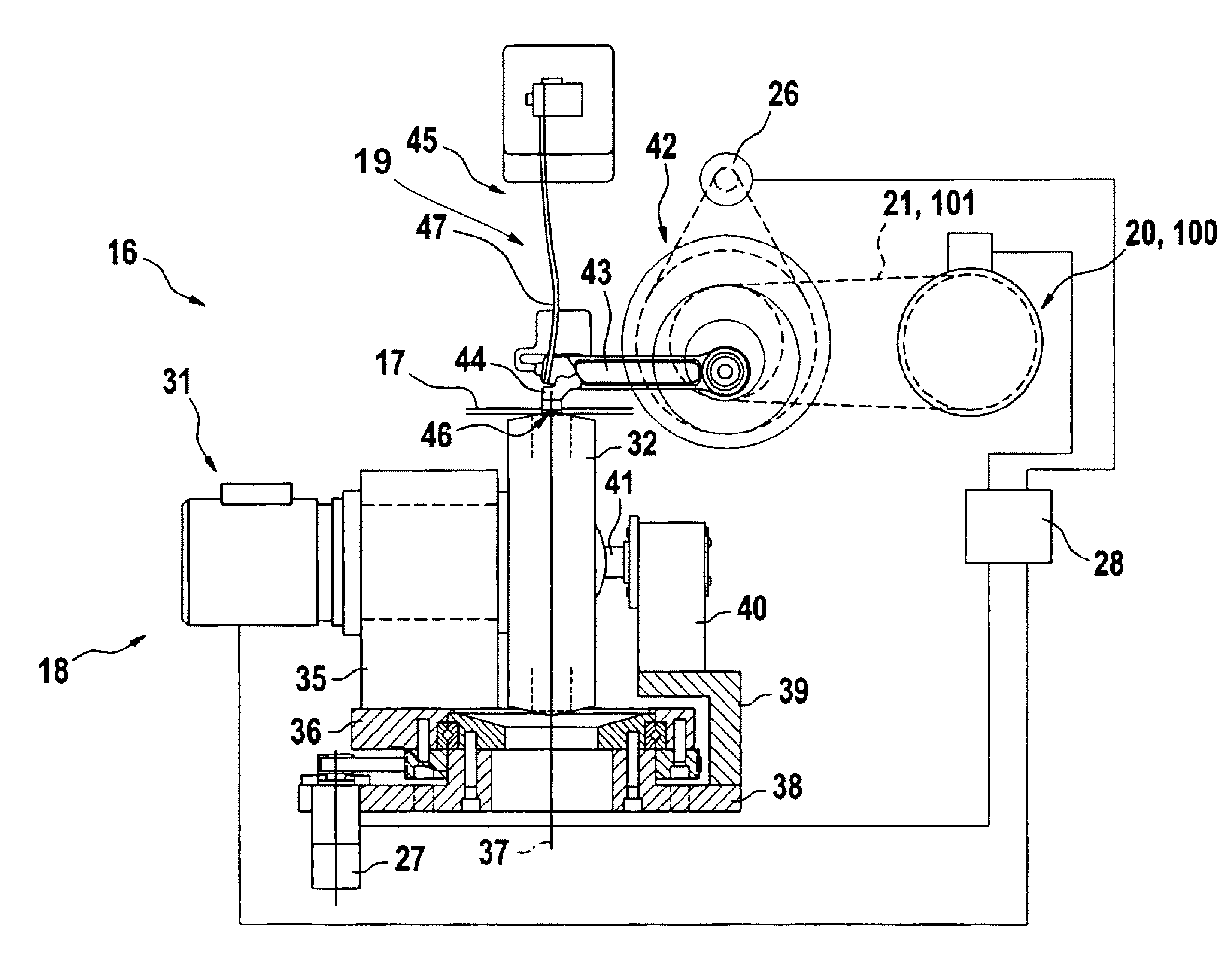
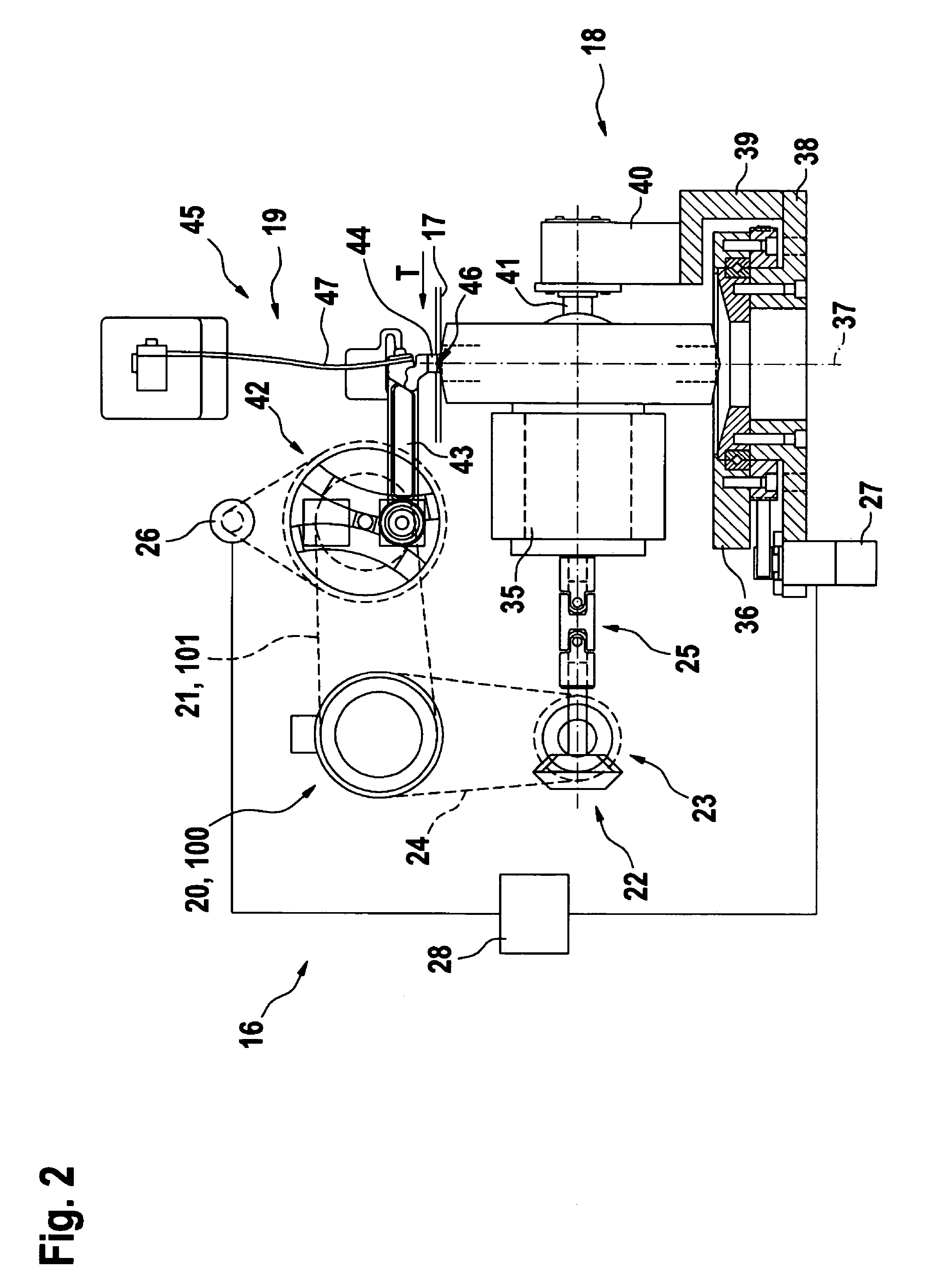
[0026]The apparatus and the method serve to cut articles off an endless rod or several parallel-guided rods of tobacco, filter material or the like with a length adjustment of the apparatus for cutting articles of variable length.

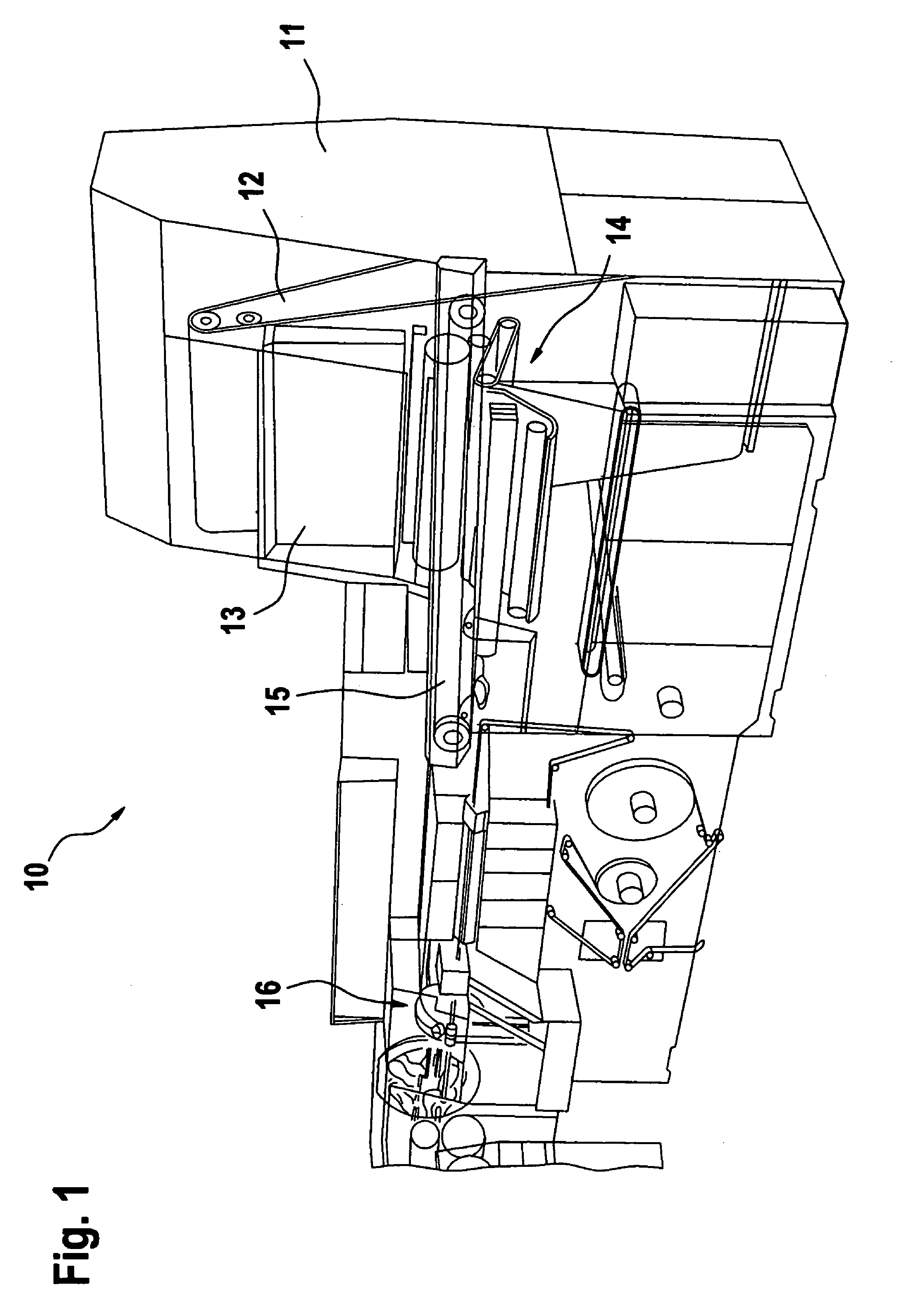
[0027]For greater clarity, with the aid of FIG. 1 first an apparatus known as a continuous rod-making machine 10 is shown, which serves to manufacture rod-shaped articles, e.g. cigarettes, filters or the like. The continuous rod-making machine 10, shown in the figure by way of example as a continuous cigarette rod-making machine, essentially includes, in addition to a storage container 11 for the material to be worked and processed, a conveyor 12 for transporting the material out of the storage container 11 to an accumulating shaft 13, means 14 for forming a rod or several parallel rods, a rod conveyor 15 and an apparatus 16 for cutting the continuously conveyed rod or several continuously conveyed rods. The continuous rod-making machine 10 can be designed ...


PUM


Abstract

The invention concerns an apparatus for cutting at least one continuously conveyed rod into rod-shaped articles of variable length, in particular cigarettes, filters or the like, including a cutting device, a counter-support and displacing devices for the cutting device and the counter-support for varying the cut length of the articles, which is characterized in that the displacing devices for the cutting device and the counter-support are coupled together to make a functional connection. Furthermore, the invention concerns a corresponding method which is characterized in that, to alter the length of the articles to be cut off the rod, only one component is displaced, namely optionally the cutting device or the counter-support, and the other component is automatically displaced with it as a function of the displaced component.

Description

CROSS-REFERENCE TO RELATED APPLICATION[0001]This application claims the priority of German Patent Application No. 10 2004 047 265.3 filed Sep. 24, 2004, the subject matter of which is incorporated herein by reference. The disclosure of all U.S. and foreign patents and patent applications mentioned below are also incorporated herein by reference.BACKGROUND OF THE INVENTION[0002]The invention concerns an apparatus for cutting at least one continuously conveyed rod into rod-shaped articles of variable length, in particular cigarettes, filters or the like, including a cutting device, a counter-support and displacing devices for the cutting device and the counter-support for varying the cut length of the articles. Further, the invention concerns a continuous rod-making machine for the manufacture of rod-shaped articles, in particular cigarettes, filters or the like, essentially including a storage container for the material to be processed, means for forming at least one continuously con...

Claims


Application Information

Patent Timeline
Patent Type & Authority Patents(United States)
IPC IPC(8): A24C5/12A24C5/28
CPCA24C5/28B26D1/28B26D7/01
Inventor JAHNKE, MATTHIASPOPP, KONRADAHLBORN, DETLEF
Owner HAUNI MASCHINENBAU AG
Why Eureka
Try Eureka