Friction device for a clutch, particularly of a motor vehicle

Inactive Publication Date: 2011-08-09
VALEO MATERIAUX DE FRICTION
View PDF22 Cites 2 Cited by
  • Summary
  • Abstract
  • Description
  • Claims
  • Application Information

AI Technical Summary

Benefits of technology

[0021]These connection tongues enable the friction lining members to move with respect to each other substantially by screwing along a rotation center axis of the supports (it will be recalled that screwing along an axis is a simultaneous combination of a rotation on this axis and a translation parallel to this same axis). Thus, when the axial separation of the friction lining members increases, the angular offset between the fixing ends of each tongue decreases, and when the axial separation of the friction lining members decreases, the angular offset between the fixing ends of each tongue increases.
[0028]it is possible to define, on each connecting tongue of the support, a top angular sector coinciding substantially with the second fixing end of this tongue and extending as far as an external contour of the support without any interruption of material, the angular sector forming an angle between 10° and 35°, and where an axis perpendicular to a radius passing through the center of the device is included in the said angular sector;
[0049]It should be noted that the connecting means of the two friction lining members can make it possible either to affix them together directly with contact (this thus means that the securing end is a connecting end), or indirectly with the presence of an intermediate piece between the two friction lining members.
[0051]It should be noted that, by virtue of the invention, which makes it possible to optimize the contact of the friction linings with the pressure and reaction plates, it is possible to reduce the radial width of these linings more than in the prior art.

Problems solved by technology

Shearing effects limit the possibilities of arranging the elastomer mass between a lining and its support.
Consequently the separation between the peripheral parts of the lining supports does not vary uniformly radially, when the friction linings are clamped between the pressure and reaction plates.
As a result the friction linings do not cooperate uniformly radially with the pressure and reaction plates, which impairs the performance of the clutch.

Method used


Image

  • Friction device for a clutch, particularly of a motor vehicle
  • Friction device for a clutch, particularly of a motor vehicle
  • Friction device for a clutch, particularly of a motor vehicle

Examples


first embodiment

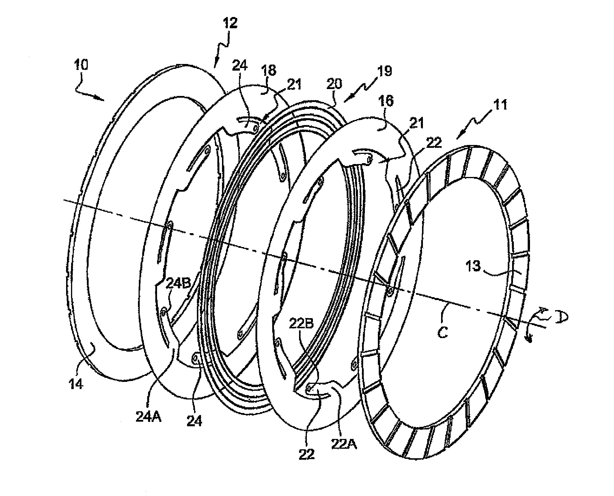
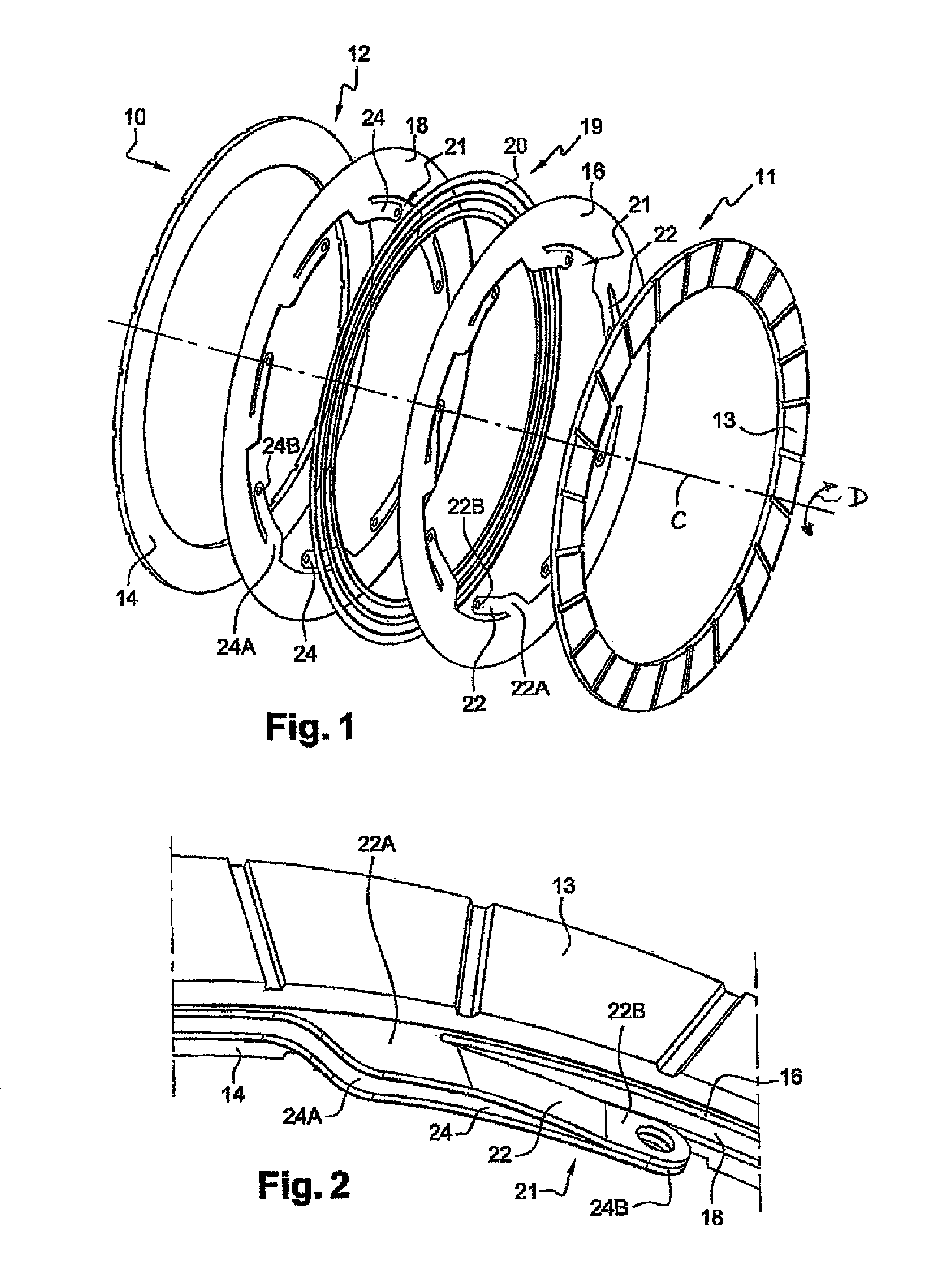
[0067]The friction device 10 comprises elastic axial bracing means 19 for the first 16 and second 18 supports, intended to provide the progressiveness of the clutch. According to the invention, the elastic bracing means 19 comprise an elastomeric member 20 preferably comprising three annular rings, substantially coaxial, arranged between the first 16 and second 18 supports.

[0068]The friction device 10 also comprises means 21 of connecting the first 16 and second 18 supports together, depicted in more detail in FIG. 2.

[0069]The connecting means 21 comprise first connecting tongues 22, each provided with a single first end 22A for fixing to an internal contour of the first support 16, and second connecting tongues 24, each provided with a single first end 24A for fixing to the internal contour of the second support 18. As depicted in FIGS. 1 and 2, the first connection tongues 22 and the second connecting tongues 24 arranged so that each one of the first connection tongues 22 is axial...

second embodiment

[0085]FIGS. 6 and 7 depict a friction device according to the invention. In these figures, the elements similar to those in the previous figures are designated by identical references.

[0086]According to this second embodiment, the bracing means 19 comprise elastic bracing tongues 28. These bracing tongues 28 are cut from the support 16 and are preferably disposed tangentially to a circle coaxial with the support 16. In a variant the bracing tongues can be disposed radially.

[0087]The elastic bracing tongues 28 are shown in more detail in FIG. 7.

[0088]Each elastic bracing tongue 24 is provided with a first end 26A for connection to the first support 16 and a second free end 28B. The bracing tongues 28 are bent so that their first 28A and second 28B ends are offset axially from each other. Thus the second end 28B of each bracing tongue 28 is able to come into contact with the second support 18, in particular when the first 16 and second 18 supports move towards each other, so as to ens...


PUM


Abstract

The invention relates to a friction device for a clutch, particularly of a motor vehicle. The inventive friction device comprises first and second axially-spaced coaxial friction lining members which are defined by opposing friction faces. The device also comprises means for linking the two friction lining members which are solidly connected to one another. The first friction lining member is essentially ring shaped. The aforementioned linking means comprise linking tongue elements which are each equipped with a first end for solidly connecting to an inner edge of the first friction lining member and a second end for solidly connecting to the second friction lining member. Moreover, a deviation angle is provided between said first and second connecting ends, which can vary according to the axial spacing of the two friction lining member.

Description

BACKGROUND OF THE INVENTION[0001]1. Field of the Invention[0002]The present invention concerns a friction device for a clutch, in particular for a motor vehicle.[0003]2. Description of the Related Art[0004]A motor vehicle clutch is intended to transmit a torque between the engine flywheel of a motor vehicle and the gearbox input shaft. To this end, the clutch comprises a mechanism, rotationally fixed to the engine flywheel, and a friction device rotationally fixed to the gearbox shaft.[0005]The mechanism comprises a pressure plate and a reaction plate, intended to cooperate with first and second friction linings of the friction device. These friction linings are carried by at least one support, normally of general form of revolution.[0006]The friction device must achieve a compromise between various technical constraints.[0007]On the one hand, it is necessary to limit the weight and inertia of the friction device.[0008]To this end, it is wished to limit the dimensions of the frictio...

Claims


Application Information

Patent Timeline
IPC IPC(8): F16D13/64F16D69/04
CPCF16D13/64F16D13/38F16D69/0408F16D2069/0458F16D2300/12
Inventor VATIN, GERAUDPINEDA, PHILIPPEDUMAS, PIERRETESSIER, VALERIE
Owner VALEO MATERIAUX DE FRICTION
Why Eureka
Try Eureka