
Sensor and method for spinal monitoring

a sensor and spinal technology, applied in the field of spinal monitoring, can solve the problems of patient pain and discomfort, and the difficulty of monitoring the condition of the anatomic structure adjacent to the spinal segment,

Active Publication Date: 2011-08-09
MEDTRONIC INC
View PDF176 Cites 41 Cited by
  • Summary
  • Abstract
  • Description
  • Claims
  • Application Information

AI Technical Summary

Problems solved by technology

Herniation of disc material or other bulges may lead to patient pain and discomfort.
However, it is currently difficult to monitor the condition of the anatomic structures adjacent a spinal segment.

Method used


Image

  • Sensor and method for spinal monitoring
  • Sensor and method for spinal monitoring
  • Sensor and method for spinal monitoring

Examples


Embodiment Construction

[0018]For the purposes of promoting an understanding of the principles of the present invention, reference will now be made to the embodiments illustrated in the drawings, and specific language will be used to describe the same. It will nevertheless be understood that no limitation of the scope of the invention is intended. Any alterations and further modifications in the described devices, instruments, methods, and any further application of the principles of the invention as described herein are contemplated as would normally occur to one skilled in the art to which the invention relates.

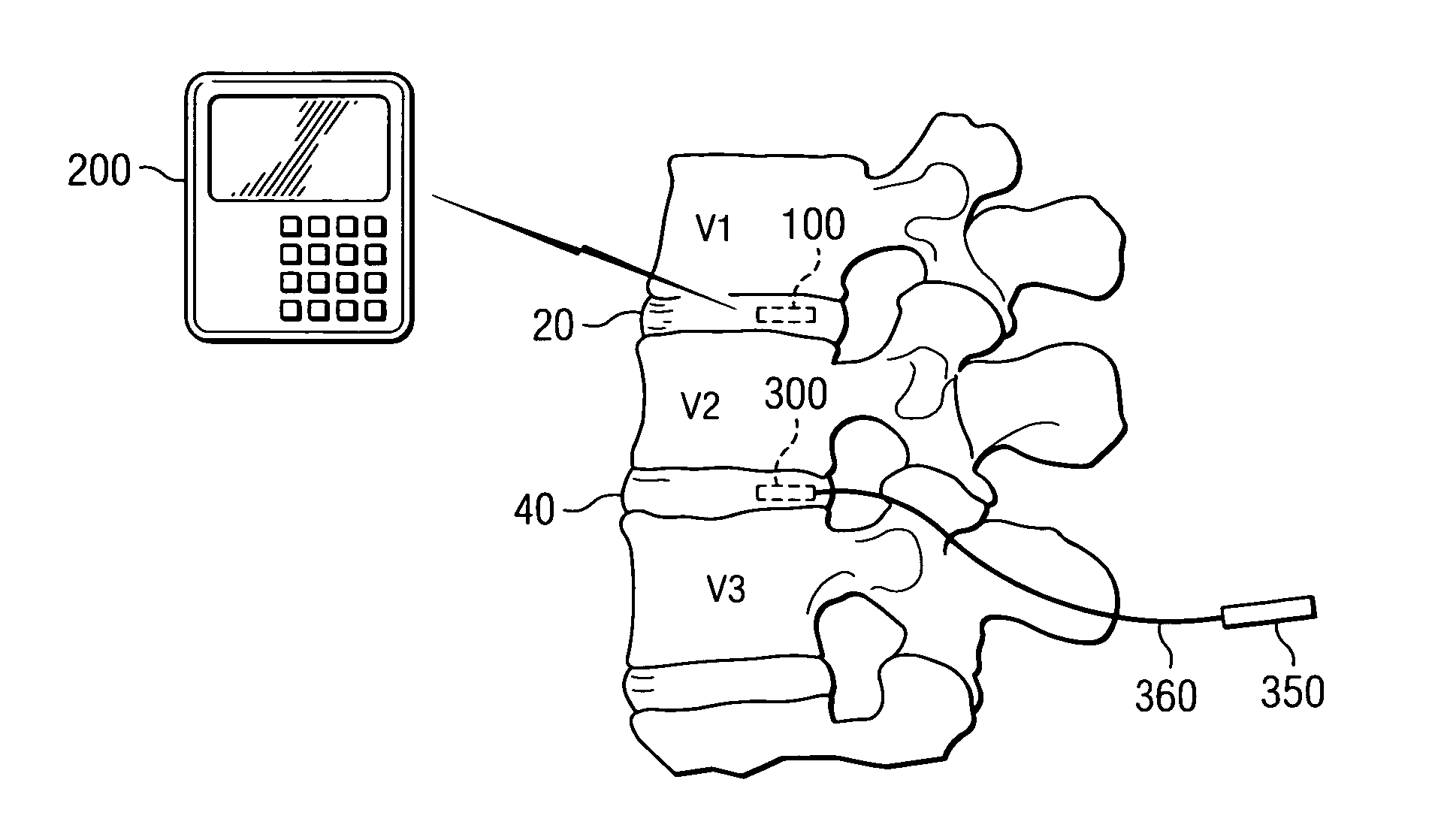
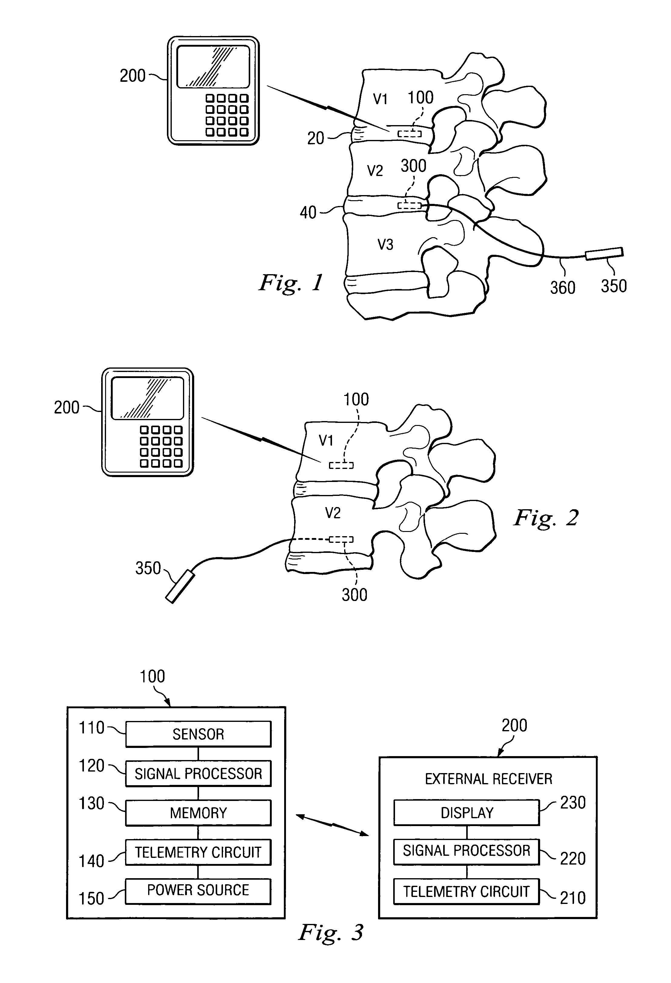
[0019]Referring now to FIG. 1, shown therein is an implantable sensor 100 for monitoring changes in tissue density in the disc space area 20 disposed at the spinal level between vertebrae V1 and V2. FIG. 1 shows the implantable sensor unit 100 in wireless communication with an external device 200. In one aspect, the implantable sensor unit 100 is configured to detect and keep track of indicators a...


PUM


Abstract

A sensor for detecting changes in spinal tissue is disclosed. The implantable sensor or surgical instrument includes a sensing element adapted for detecting indicators of tissue health. The sensor is configured for transmitting the tissue data outside of the body. Further a system and method are provided to utilize the sensed tissue properties to treat the patient's condition.

Description

FIELD OF THE INVENTION[0001]The present invention is directed to improved instrumentation and methods for monitoring the condition of the spine. More particularly, in one aspect the present invention is directed to a sensor for detecting changes at a spinal level associated with degeneration or injury to the spinal segment.BACKGROUND OF THE INVENTION[0002]The present invention relates to the sensing changes in tissues associated with a spinal level. The invention may be particularly useful in the assessment of tissue density as it relates to the intradiscal environment. Herniation of disc material or other bulges may lead to patient pain and discomfort. Being able to detect the onset of these conditions may allow early medical intervention to treat the condition, stop its advance or slow the progression. However, it is currently difficult to monitor the condition of the anatomic structures adjacent a spinal segment. Thus, there is a need for a device and system that is able to monit...

Claims


Application Information

Patent Timeline
Patent Type & Authority Patents(United States)
IPC IPC(8): A61B5/00A61B5/103
CPCA61B5/0031A61B5/076A61B5/1116A61B5/4509A61B5/4514A61B5/6878Y10S128/903A61B2560/0214A61B2562/043
Inventor DONOFRIO, WILLIAM T.NYCZ, JEFFREY H.TETHRAKE, STEVENOLSON, JR., STANLEY WARREN
Owner MEDTRONIC INC
Learn More