Frac tank storage system

a storage system and frac tank technology, applied in the field of storage tanks, can solve the problems of requiring significant ground space, not always the most economical method of transportation, and significantly more expensive per floor space than in the container stack, so as to reduce freight expense, cost effective, and reasonable cost

Inactive Publication Date: 2011-08-16
CHRIS WILLIAMS
View PDF9 Cites 92 Cited by
  • Summary
  • Abstract
  • Description
  • Claims
  • Application Information

AI Technical Summary

Benefits of technology

[0015]Briefly, one preferred frac tank system, according to the invention, includes a frac tank with front and rear frac-tank elements (e.g., valves, valve connections, hose connections, access ports), a front fifth-wheel king pin, rear over-the-road axle and wheel support for highway speed travel, and removable front and rear adapter structures. The adapter structures surround and protect the front and back frac tank components that may be otherwise exposed during transportation and storage. More importantly, in accordance with the invention, the adapter structures convert the frac tank between a mobile condition with the wheels and king pin exposed to be pulled by a fifth-wheel equipped vehicle, and a containerized condition with an overall conventional shipping container configuration, including outer dimensional size, pickup and support locations, and structural supporting strength, to achieve handling, stacking and shipping interchangeability with conventional shipping containers. The adapter structures are secured to the ends of the mobile frac tank, to adapt the tank for shipping as a standard freight container. The adapter structures are removed from the tank to haul it down the road by a semi-tractor hooked to the fifth wheel, to pull the tank down the road on its wheels. The adapter structures unbolt from the ends of the tank and can be reattached at a later time if the tank is to be again shipped as standard freight. The preferred adapter structures each comprise a framework that can be bolted or otherwise removably secured to the ends of a frac tank to achieve the containerized configuration, and thin covers that may be secured to the framework for additional protection to the operational or front and rear elements of the frac tank.
[0016]By virtue of its flexible shipping options, the frac tank system can significantly reduce freight expense by enabling use of the most cost effective method of transport for a particular job (e.g., via tractor trailer, flatbed, rail), and the system can be shipped at a reasonable cost to destinations that would otherwise be cost prohibitive for shipping of conventional frac tanks due to their required placement in the bulk area of the ship.
[0017]By virtue of the expanded shipping options, the frac tank system will have an increased potential service area as compared with conventional frac tanks, and more frac tanks can be delivered to distant sites sooner and more economically than conventional frac tanks
[0018]By virtue of its containerized configuration, the frac tank system can significantly reduce freight cost on international shipping due to placement in the regular stacks rather than the more expensive bulk area.
[0019]By virtue of its containerized configuration, the frac tank system permits stacking of tanks during downtime to reduce required storage area and costs as compared with storage of conventional frac tanks
[0020]By virtue of its containerized configuration, including corner crane pockets, the frac tank system allows for expanded job site options and ease of on-site placement as compared with the conventional mobile frac tank. As a result, the frac tank system reduces operational footprint in ever smaller and environmentally sensitive sites.

Problems solved by technology

However, transport by such means is not always the most economical method of transport.
Where overseas shipping is involved, such conventional frac tanks need to be located in the “bulk area” of the ship, which is significantly more expensive per floor space than in the container stacks on the ship.
This can require significant ground space.

Method used


Image

  • Frac tank storage system
  • Frac tank storage system
  • Frac tank storage system

Examples


Embodiment Construction

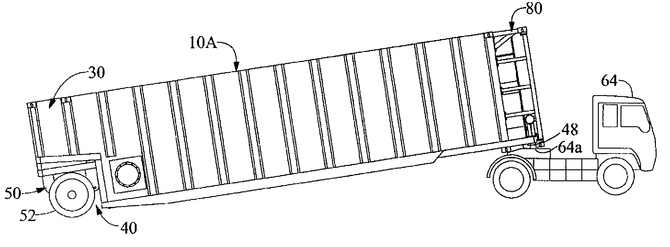
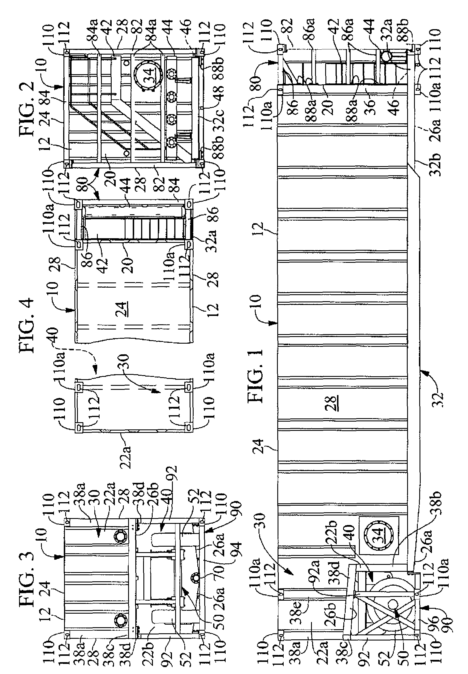
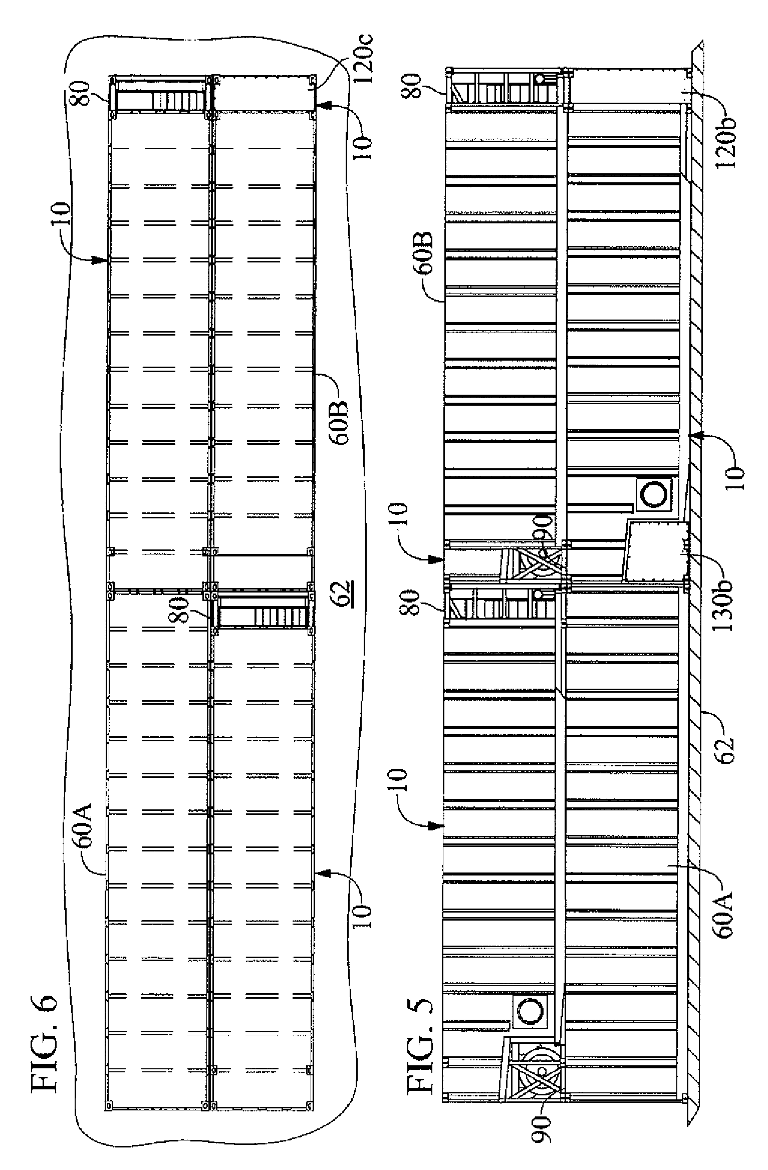
[0050]The present invention is shown in the drawings as embodied in frac tank system 10 (FIGS. 1-4) for holding fluid at an oil well site, to be pumped into the oil well during drilling operations. In accordance with the invention, the frac tank system 10 is configured for alternate (i) placement, stacking and shipping with other frac tank systems, as well as with conventional containers 60A and 60B such as in the container cargo stacks on, for example, the deck 62 of a barge or a ship as shown in FIGS. 5-6, and (ii) mobile transport with, for example, a semi-tractor 64 such as shown in FIG. 26. More particularly, the frac tank system 10 is configured for conversion between a containerized condition as shown in FIGS. 1-6, and a mobile condition such as indicated by reference numeral 10A in FIGS. 26 and 7-10.

[0051]The preferred frac tank system 10 conforms to international shipping container standards, such as the generally accepted ISO standards for freight containers, sufficient st...


PUM


Abstract

A frac tank, configured for containerized handling, stacking and shipping in container cargo stacks, includes rear over-the-road axle and wheel support, a rear adapter for selectively exposing the rear wheels to enable mobile transport with a fifth-wheel equipped vehicle, and a front adapter for selectively exposing elements at the front of the tank during on-site use of the tank.

Description

RELATED APPLICATIONS[0001]This application is a continuation of application PCT / US2009 / 050436 with an international filing date of Jul. 13, 2009 and which in turn claims priority to U.S. Provisional Application No. 61 / 080,259 filed Jul. 13, 2008. The entire specification and drawings of the aforementioned applications are incorporated by reference herein as if fully set forth.BACKGROUND OF THE INVENTION[0002]1. Field of Invention[0003]This invention relates generally to a storage tank.[0004]More particularly, the invention relates to a storage tank, commonly known as a frac tank, to hold fluid for use in oil well drilling operations, and to a transportation and storage system including a frac tank.[0005]2. Background Art[0006]Frac tanks are used to hold fluid, sometimes referred to as drilling fluid or fracturing fluid, or a liquid constituent or mixture therefor, for pumping into an oil well during drilling operations.[0007]Some conventional frac tanks are configured to be pulled w...

Claims


Application Information

Patent Timeline
Patent Type & Authority Patents(United States)
IPC IPC(8): B60P3/22
CPCB60P3/2215B65D88/128B65D90/18B65D2590/0091
Inventor WILLIAMS, CHRIS
Owner CHRIS WILLIAMS
Why Eureka
Try Eureka