Rotary pressure transfer device with improved flow

a technology of pressure transfer device and flow rate, which is applied in the direction of positive displacement liquid engine, piston pump, membrane, etc., can solve the problems of reducing efficiency, reducing device efficiency, and reducing device efficiency, so as to protect against substantial fluctuations in the rate of feed flow and minimize liquid mixing.

Active Publication Date: 2011-08-16
ENERGY RECOVERY INC
View PDF13 Cites 39 Cited by
  • Summary
  • Abstract
  • Description
  • Claims
  • Application Information

AI Technical Summary

Benefits of technology

[0006]As a result, other solutions to minimize mixing of liquids in rotary pressure transfer devices of this type and to guard against substantial fluctuations in rates of feed flow have been sought.
[0007]It has now been found that if oblique ramps that each create directional inlet flow to cause the rotation of the rotor are included only in the inlet and discharge passageways on the high-pressure side and the low-pressure liquid is allowed to flow into and out of the channels in an essentially longitudinal direction, not only can a pressurized second liquid stream be delivered that shows minimal evidence of mixing, but other significant operational advantages follow along with such minimization of mixing.
[0021]the improvement which comprises oblique ramps in said high pressure inlet and discharge passageways in said end covers which cause directional flow of high pressure fluid into and out of said rotor channels to provide force that causes said rotor to revolve in a first angular direction, and reverse oblique ramps in said low-pressure inlet and discharge passageways which cause directional flow of low-pressure fluid into and out of said rotor channels in a manner which tends to retard the revolution of the rotor in the first angular direction.

Problems solved by technology

In some instances, it is particularly important to minimize the amount of mixing that occurs between the two liquids; however, there is a reluctance to reduce the efficiency of the pressure transfer device to achieve such an end.
However, such solutions to the problem of mixing are felt to not only reduce efficiency by occupying a part of the volume of each channel, but also complicate the device by requiring complex controls to prevent pistons from slamming into one of the ends of the channel.

Method used


Image

  • Rotary pressure transfer device with improved flow
  • Rotary pressure transfer device with improved flow
  • Rotary pressure transfer device with improved flow

Examples


Embodiment Construction

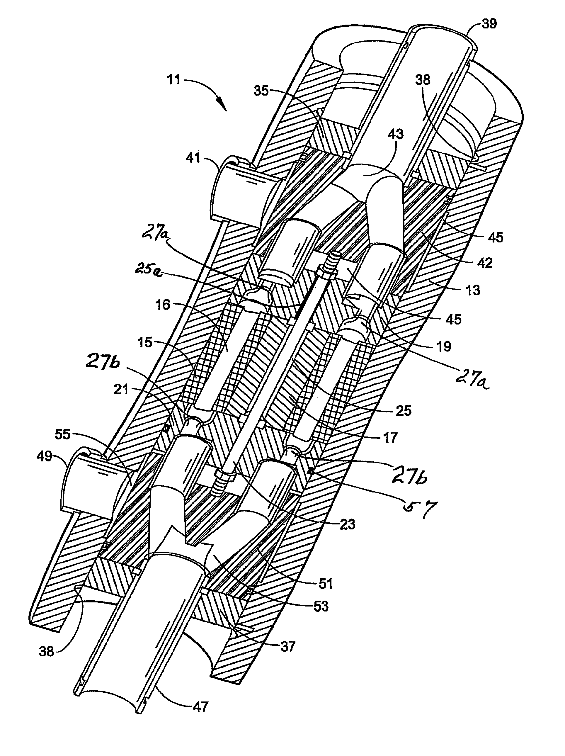
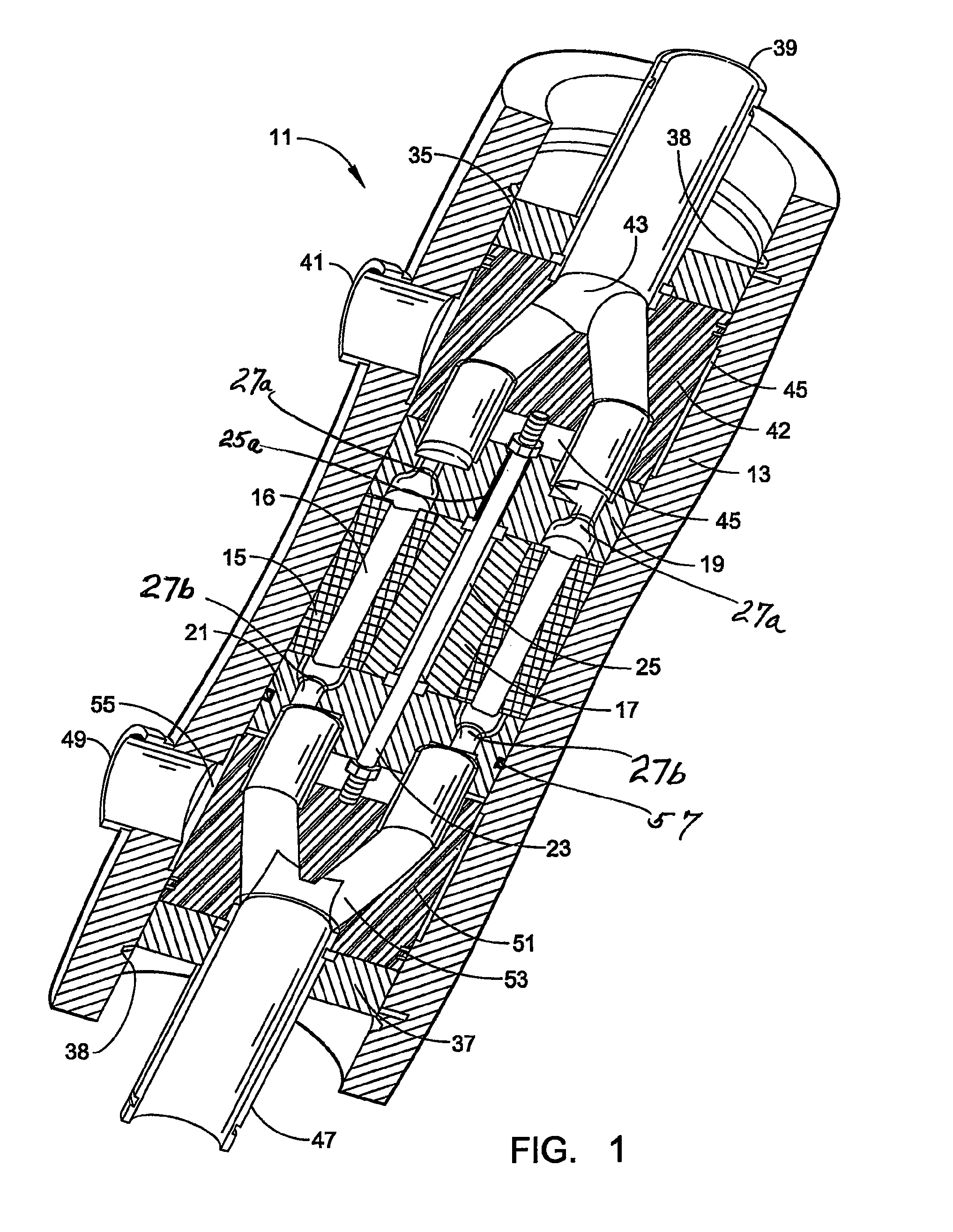
[0027]It has now been found that it is practical to employ end covers with oblique ramps only on the high-pressure side. As a result, the entry of high-pressure liquid drives rotor motion while the entry of low-pressure liquid has no effect on rotor motion. One result of such an arrangement is an increase in the flow rate of low-pressure liquid, which can be adjusted to substantially flush the rotor in each fill, e.g. by significantly displacing brine and replacing it with relatively low-salinity seawater when employed in a desalination operation, without changing the rotor speed. Generally, in a reverse osmosis desalination system, the flow rate of the high pressure brine being delivered to the pressure transfer device will be substantially constant, i.e., generally steady and without significant variation. However, the flow rate of the low pressure seawater inflow may occasionally spike upwards which might momentarily change rotor speed where both flows are being used to power the...


PUM


Abstract

A rotary pressure transfer device utilizes a multi-channel, generally cylindrical rotor (15) that revolves with its flat end faces juxtaposed with flat end surfaces of a pair of flanking end covers (19, 21) in which inlet and outlet passageways are provided. The design is such that there are only oblique ramps (65) in the passageways on the high pressure side which create directional flow of liquid to cause rotor revolution in the desired direction. Passageways (27a, 27b) on the low pressure side may be shaped so that there is essentially axial or longitudinal flow entry and discharge of liquid between the channels and the passageways, or passageways (71) may be constructed to create directional flow that slightly retards rotor revolution in such desired direction.

Description

CROSS REFERENCE TO RELATED APPLICATIONS[0001]This application is a continuation of International Application No. PCT / US08 / 078961, filed Oct. 6, 2008, which claims priority from U.S. Provisional Application No. 60 / 977,789, filed Oct. 5, 2007, the disclosures of both of which are incorporated herein by reference.FIELD OF THE INVENTION[0002]This invention relates to rotary pressure transfer devices where a first fluid, under a high pressure, hydraulically communicates with a second, lower pressure fluid to transfer pressure between the fluids and produce a high pressure discharge stream of the second fluid. More particularly, the invention relates to such rotary, pressure transfer devices wherein end cover designs are improved to decrease mixing of the fluids in the device and better control overall operation.SUMMARY OF THE INVENTION[0003]Present day rotary pressure transfer devices employ a rotor having a plurality of channels that are often reasonably widely spaced apart and a pair o...

Claims


Application Information

Patent Timeline
Patent Type & Authority Patents(United States)
IPC IPC(8): F01D15/08F04B35/00
CPCB01D61/06B01D61/10C02F1/441C02F2103/08Y02A20/131F04F13/00C02F2303/10B01D2313/246
Inventor PIQUE, GONZALO G.STOVER, RICHARD L.MARTIN, JEREMY G.PINTO, JUAN MIGUEL
Owner ENERGY RECOVERY INC
Why Eureka
Try Eureka