Method of separating foreign particles

a technology of foreign particles and separation methods, applied in the field of separation methods, can solve the problems of affecting the practical use of the intended material, affecting the separation efficiency, so as to achieve high purity, high concentration rate, and high yield

Active Publication Date: 2011-08-16
TAIHEIYO CEMENT CORP
View PDF15 Cites 0 Cited by
  • Summary
  • Abstract
  • Description
  • Claims
  • Application Information

AI Technical Summary

Benefits of technology

[0014]According to the present invention, it is possible to recover only intended material particles with high purity (high concentration rate) and with high yield, from the mixed powder containing the intended material particles and unintended material particles. As a result, the recovered intended material particles can be efficiently used, which leads to a large contribution to the future effective use of resources and environmental measures on a global scale, from perspectives of effective use of resources, and effective use of by-product and waste.

Problems solved by technology

It has been discovered that significant factors other than factors conventionally and commonly known have an adverse effect on separation and recovery efficiency and separation efficiency such as concentration rate of an intended material, and hinder practical uses thereof.
However, when an experiment is actually carried out in a dried state, it is found that a part of particles has relatively high separation efficiency, while many particles have an extremely insufficient separation efficiency which is not developed to a practical level at all.
As a result, it has been discovered that, in either case of the electrostatic separation and the magnetic separation, when a large amount of fine powder having a spherical equivalent diameter of 10 μm or smaller is contained in the mixed powder of particles having different properties, the separation efficiency is reduced to a large extent.

Method used


Image

  • Method of separating foreign particles
  • Method of separating foreign particles
  • Method of separating foreign particles

Examples


example 1

[0028]About 10 million tons of fly ash are generated from electric power plants across the country. From the viewpoint of the future effective use of resources, low-grade coal whose ash content is high is used in many cases, and it is expected that the yield of the fly ash is to be further increased. About 60% of the fly ash is used as a part of a raw material of cement in the production of cement, and an available quantity of the fly ash has already reached its limit from the viewpoint of a chemical component as cement. Most of the remaining fly ash is landfilled. The landfill is not desirable in view of environmental measures as a matter of course.

[0029]In order to further increase the available quantity of the fly ash in the field of cement, instead of using the fly ash as the raw material of cement, it is necessary to add and mix the fly ash to produced cement within a range as defined by Japanese industrial standards (JIS). However, under the present circumstances, unburned car...

example 2

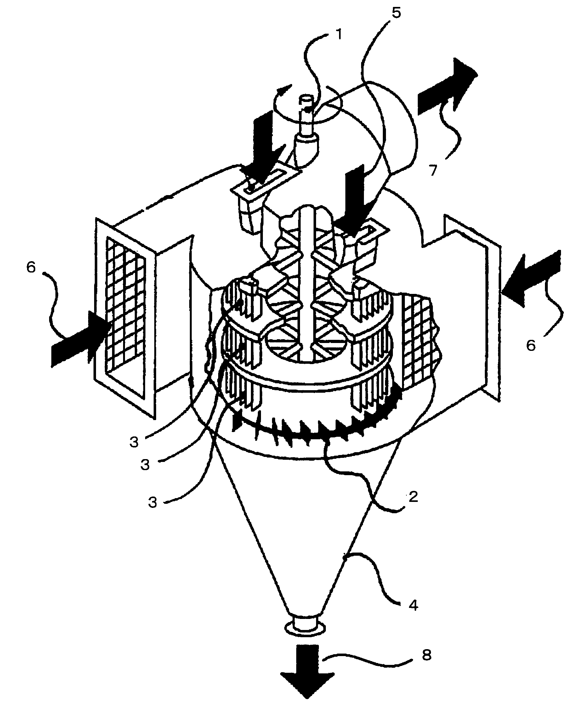
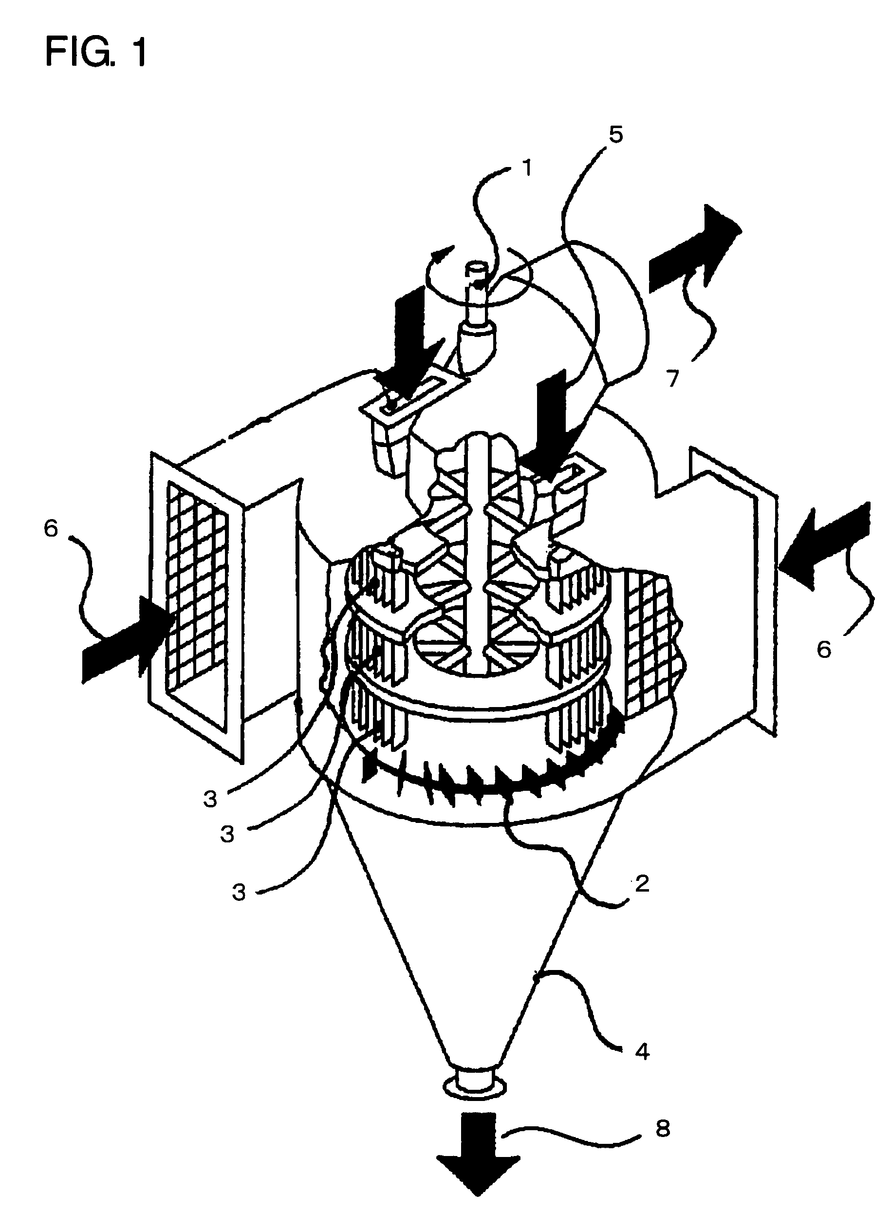
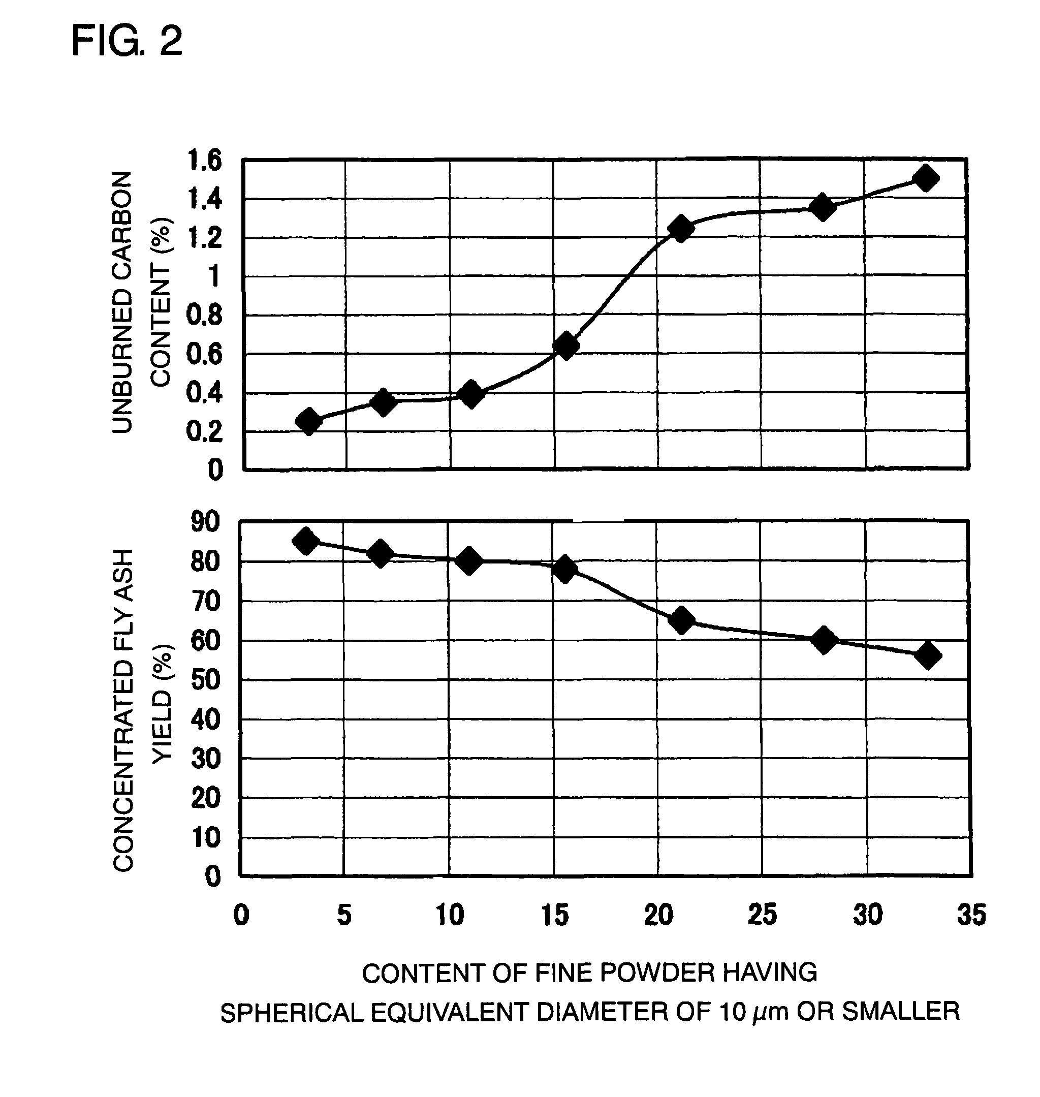
[0035]In Example 2, the same fly ash as that of Example 1 was used, the centrifugal classifier having the structure as shown in FIG. 1 was used to classify the fly ash, a pin-type dispersing apparatus as shown in FIG. 3 was used to disperse the fly ash, and an electrostatic separator was used, to thereby carry out the experiment. Note that in FIG. 3, reference numeral 9 denotes raw material powder; 10, a motor; and 11, pins. A rotational speed of the pins 11 was set to 30 m / s. A part of the results is shown in FIG. 4. FIG. 4 shows that, as compared to the results of Example 1, the unburned carbon content is further reduced and the concentrated fly ash yield is improved.


PUM

PropertyMeasurementUnit
diameteraaaaaaaaaa
humidityaaaaaaaaaa
humidityaaaaaaaaaa

Abstract

In an electrostatic separator or a magnetic separator, prior to electrically charging or magnetization of particles in order to carry out separation of mixed powder of particles having different properties from each other, classification is performed by a classifier so that the content of fine powder having a spherical equivalent diameter of 10 μm or smaller is 15 mass % or less. After the classification, prior to electrostatic separation or magnetic separation, an operation of dispersing the mixed powder of particles may be carried out.

Description

BACKGROUND OF THE INVENTION[0001]1. Technical Field[0002]The present invention relates to a separation method capable of providing an economically satisfactory separation and recovery efficiency or a removal efficiency, and of providing a concentration rate of an intended component with a sufficient level that withstands practical use thereof, in a case of carrying out separation and recovery of an intended material or carrying out separation and removal of an unnecessary component, from powders of various minerals or from powders of intermediate products or wastes discharged from a variety of industries, by using static electricity or magnetism.[0003]2. Description of Related Art[0004]As a method of carrying out separation and recovery of an intended material from powder containing particles with different components or materials, carrying out removal of an unnecessary material, or carrying out concentration of the intended material, there are conventionally employed various method...

Claims


Application Information

Patent Timeline
Patent Type & Authority Patents(United States)
IPC IPC(8): B03C7/00
CPCB03C1/01B03C1/30B03C7/06B07B7/083
Inventor ITO, MITSUHIRO
Owner TAIHEIYO CEMENT CORP
Why Eureka
Try Eureka