Imaging lens, imaging device, and mobile terminal

a technology of imaging device and lens, applied in the field of imaging lens, can solve the problems of difficult to form diffracting surface and refracting interface simultaneously on the lens flat plate, and achieve the effect of greater curvatur

Inactive Publication Date: 2011-08-16
KONICA MINOLTA OPTO
View PDF19 Cites 10 Cited by
  • Summary
  • Abstract
  • Description
  • Claims
  • Application Information

AI Technical Summary

Benefits of technology

[0075]According to the present invention, in order to satisfy the conditional relationship, the object-side surface of the (i−1)the lens disposed on the object side of the i-th lens has a greater curvature in the vicinity of a point where the most off-axial ray passes through than in the vicinity of the optical axis. By selecting an appropriate surface shape for this curved surface, an incidence angle of the off-axial ray into the solid-state image sensor is controlled even when the aspheric surface sag amount of the ib-th lens element.
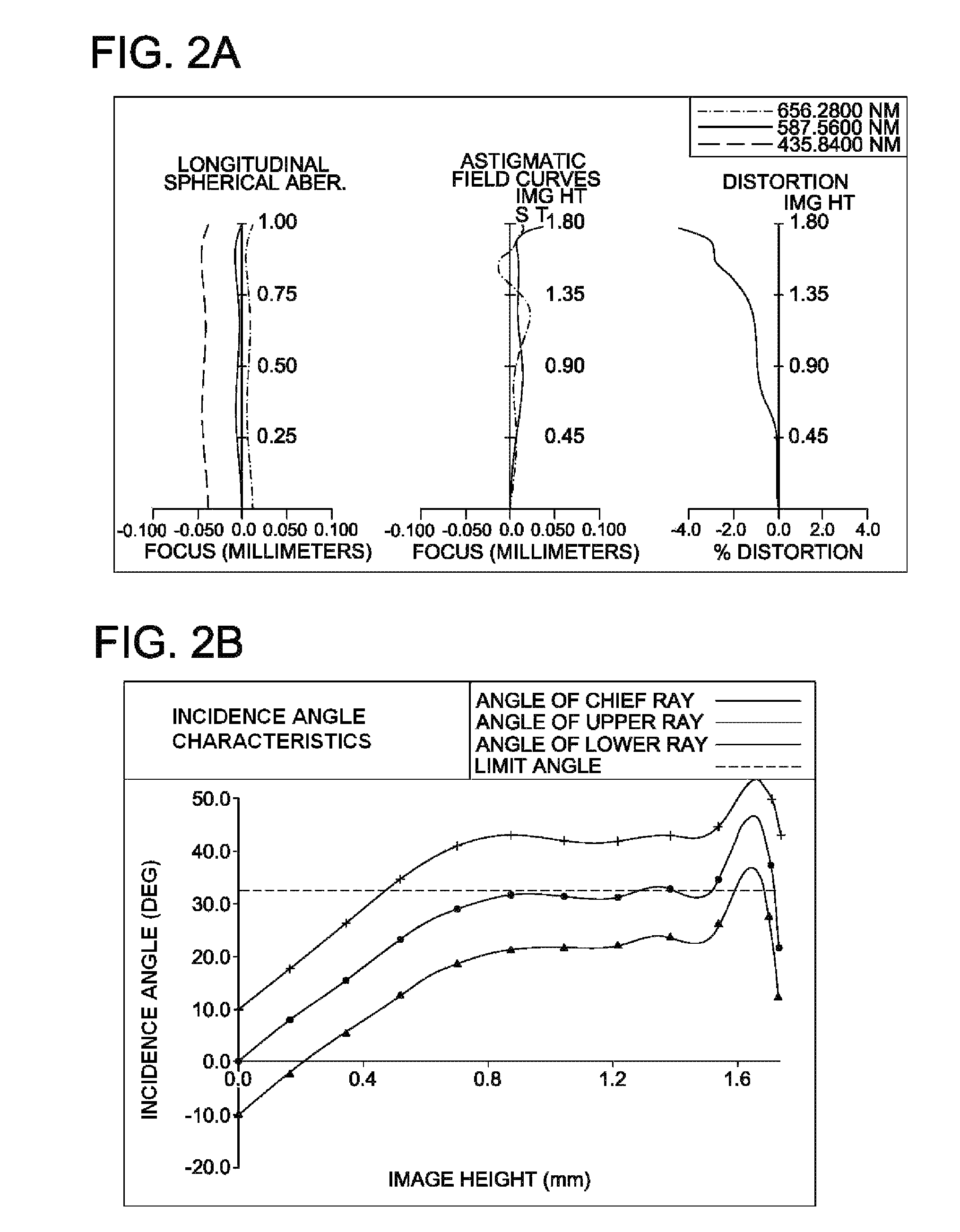
[0076]It is more preferable that a lens element is formed on both of the object side and the image side of the i-th lens flat plate, and in that case, the incidence angle of the peripheral light into the solid-state image sensor is more precisely controlled. For example, it is possible to vary the incidence angle between the vicinity of a 60% image height and higher than 90% image height, as shown in the embodiments.

Problems solved by technology

However, there is a technical limitation to achieving both of further microminiaturization of these optical systems and a mass-production capability required for use in a personal digital assistant.
However, it is not easy to form a diffracting surface and a refracting interface simultaneously on a lens flat plate.
There are problems, in use of diffracting surface, that the diffraction efficiency decreases in wavelengths other than a design wavelength and that there is a large restriction to the angle of the incident light entering into the diffracting surface due to the poor angle characteristic of the incident light to the diffracting surface.
Thus, there is a problem of difficulty in securing a wide field angle.
In an optical system given in a patent reference No. 1, although the thickness of a lens element is not thick, there is a problem of a large astigmatism.
In this technique, in the case where the thickness of UV hardening type resin section is approximately greater than 0.25 (mm), there is a problem that a penetration of ultraviolet rays is poor and UV hardening type resin cannot be hardened sufficiently.

Method used


Image

  • Imaging lens, imaging device, and mobile terminal
  • Imaging lens, imaging device, and mobile terminal
  • Imaging lens, imaging device, and mobile terminal

Examples


first embodiment

of the Present Invention

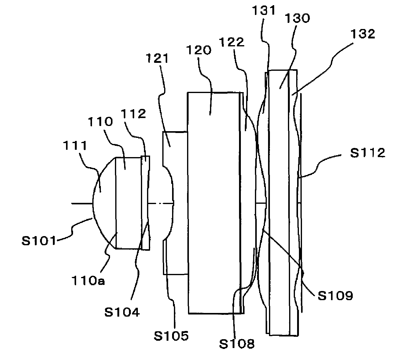
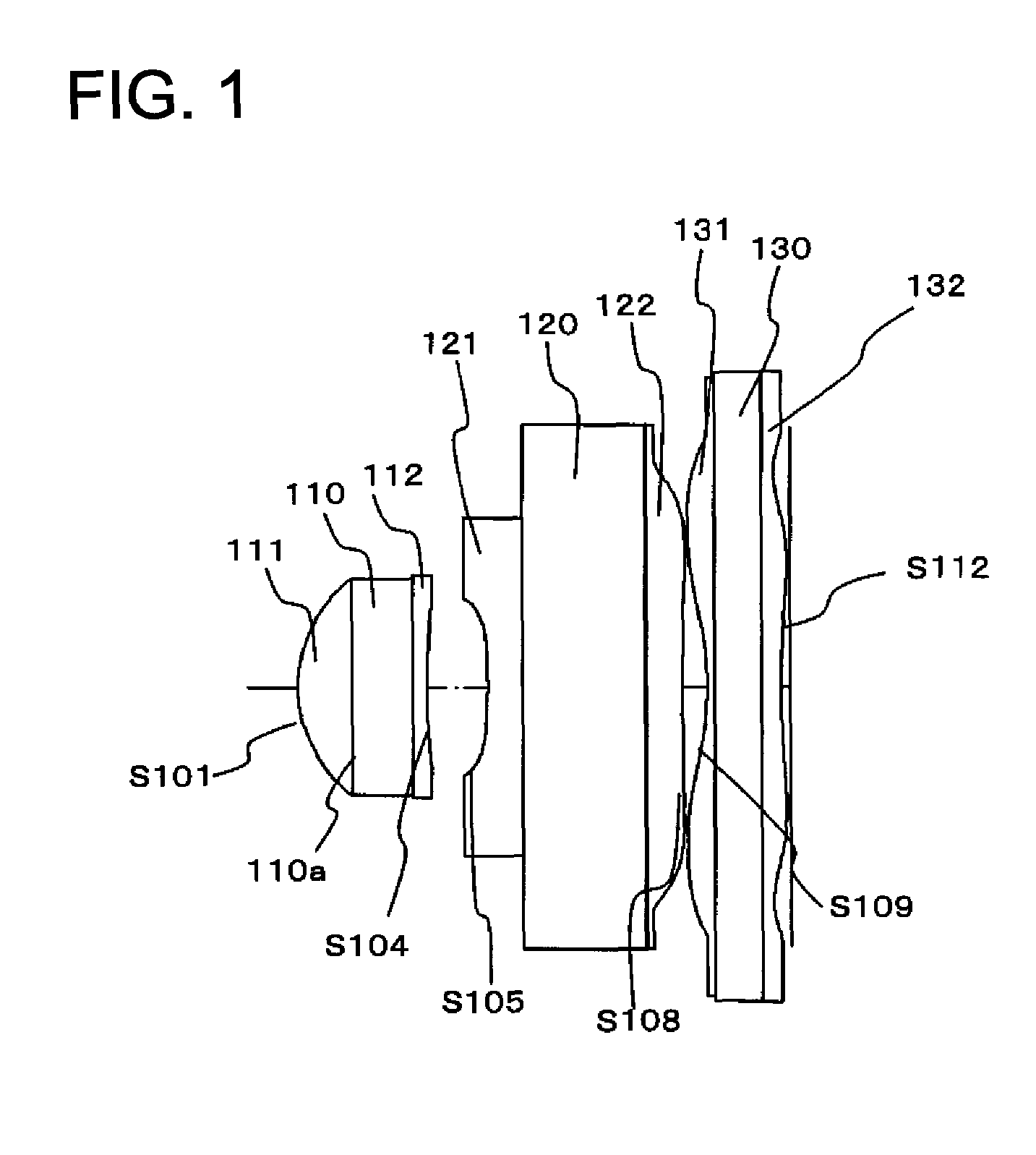
[0134]Hereinafter, an imaging lens according to a first embodiment of the present invention will be described. FIG. 1 illustrates a sectional view of the imaging lens according to this embodiment of the present invention.

[0135]As illustrated in FIG. 1, the imaging lens according to this embodiment of the present invention is configured of a lens system including a 1f-th lens element 111, an aperture diaphragm 110a, a first lens flat plate 110, a 1b-th lens element 112, a 2f-th lens element 121, a second lens flat plate 120, a 2b-th lens element 122, a 3f-th lens element 131, a third lens flat plate 130 and a 3b-th lens element 132 in the order from the object side. Here, the imaging lens configured of three lenses is described in this embodiment. However, the imaging lens may be configured of more lenses. For example, in the case where “i” (i>=4) number of lenses are used, an i-th lens disposed at the most image side may be configured similar to the third len...

second embodiment

[0145]FIG. 3 illustrates a sectional view of the imaging lens according to an second embodiment of the present invention.

[0146]As illustrated in FIG. 3, the imaging lens according to this embodiment of the present invention is configured of a lens system including a 1f-th lens element 211, an aperture diaphragm 210a, a first lens flat plate 210, a 1b-th lens element 212, a 2f-th lens element 221, a second lens flat plate 220, a 2b-th lens element 222, a 3f-th lens element 231, a third lens flat plate 230 and a 3b-th lens element 232 in the order from the object side. Here, the imaging lens configured of three lenses is described in this embodiment. However, the imaging lens may be configured of more lenses. For example, in the case where “i” (i≧4) number of lenses are used, an i-th lens disposed at the most image side may be configured similar to the third lens in this embodiment. In this case, any kind of lens (for example, a bonded lens, a spherical lens or an aspherical lens) may...

third embodiment

[0154]FIG. 5 illustrates a sectional view of the imaging lens according to a third embodiment of the present invention.

[0155]As illustrated in FIG. 5, the imaging lens according to this embodiment of the present invention is configured of a lens system including a 1f-th lens element 311, an aperture diaphragm 310a, a first lens flat plate 310, a 1b-th lens element 312, a 2f-th lens element 321, a second lens flat plate 320, a 2b-th lens element 322, a 3f-th lens element 331, a third lens flat plate 330 and a 3b-th lens element 332 in the order from the object side. Here, the imaging lens configured of three lenses is described in this embodiment. However, the imaging lens may be configured of more lenses. For example, in the case where “i” (i>=4) number of lenses are used, an i-th lens disposed at the most image side may be configured similar to the third lens in this embodiment. In this case, any kind of lens (for example, a bonded lens, a spherical lens or an aspherical lens) may ...


PUM


Abstract

Provided is an imaging lens, including, in order from an object side: a positive first lens; a second lens having a concave shape toward the object side; and (i−2) number of lens, wherein the i-th lens, which is the most image-side lens, includes: an i-th lens flat plate; and a positive or negative lens element on at least one of the opposite surfaces of the i-th lens flat plate, wherein the following conditional relationship is satisfied: 0.9>Ymax / Y>0.61, where: Ymax is a height of the most off-axial ray on an image-side surface of the (i−1)th lens; and Y is a maximum image height.

Description

RELATED APPLICATIONS[0001]This application is a U.S. National Phase Application under 35 USC 371 of International Application PCT / JP2008 / 061558 filed Jun. 25, 2008, which claims priority from Japanese Patent Application No. 2007-176624 filed Jul. 4, 2007.TECHNICAL FIELD[0002]The present invention relates to an imaging lens for photographing a subject, and an imaging lens of an imaging device using solid-state image sensing devices such as a CCD image sensor and a CMOS image sensor. In detail, the present invention relates to an image imaging lens in an optical system using a wafer-scale lens that is suitable for mass production and an imaging device using the imaging lens.BACKGROUND ART[0003]Small and thin imaging devices have come to be installed in personal digital assistants, which are small-sized and thin electronic equipment, such as a portable telephone and a PDA (Personal Digital Assistant). Whereby, it is possible to mutually transmit not only voice information but also imag...

Claims


Application Information

Patent Timeline
Patent Type & Authority Patents(United States)
IPC IPC(8): G02B9/12G02B3/02G02B9/14
CPCG02B13/0035G02B13/004G02B13/006G02B13/18G02B13/00G02B9/00H04N23/00
Inventor HIRAO, YUSUKEMATSUSAKA, KEIJIFUKUTA, YASUNARI
Owner KONICA MINOLTA OPTO
Why Eureka
Try Eureka