Covering panel

Active Publication Date: 2011-08-23
KAINDL FLOORING GMBH
View PDF35 Cites 29 Cited by
  • Summary
  • Abstract
  • Description
  • Claims
  • Application Information

AI Technical Summary

Benefits of technology

[0009]An aspect of the present invention is to provide a cladding panel of the type mentioned at the outset, which may be u

Problems solved by technology

One problem that generic cladding panels always have to deal with in practice is seasonal variations in relative humidity.
Cracks may also form from the effects of static and mechanical-dynamic stresses exerted on the floor, e.g., by heavy pieces of furniture or by walking on it.
With rectangular cladding panels this crack formation problem occurs particularly at the short sides o

Method used


Image

  • Covering panel
  • Covering panel
  • Covering panel

Examples


Embodiment Construction

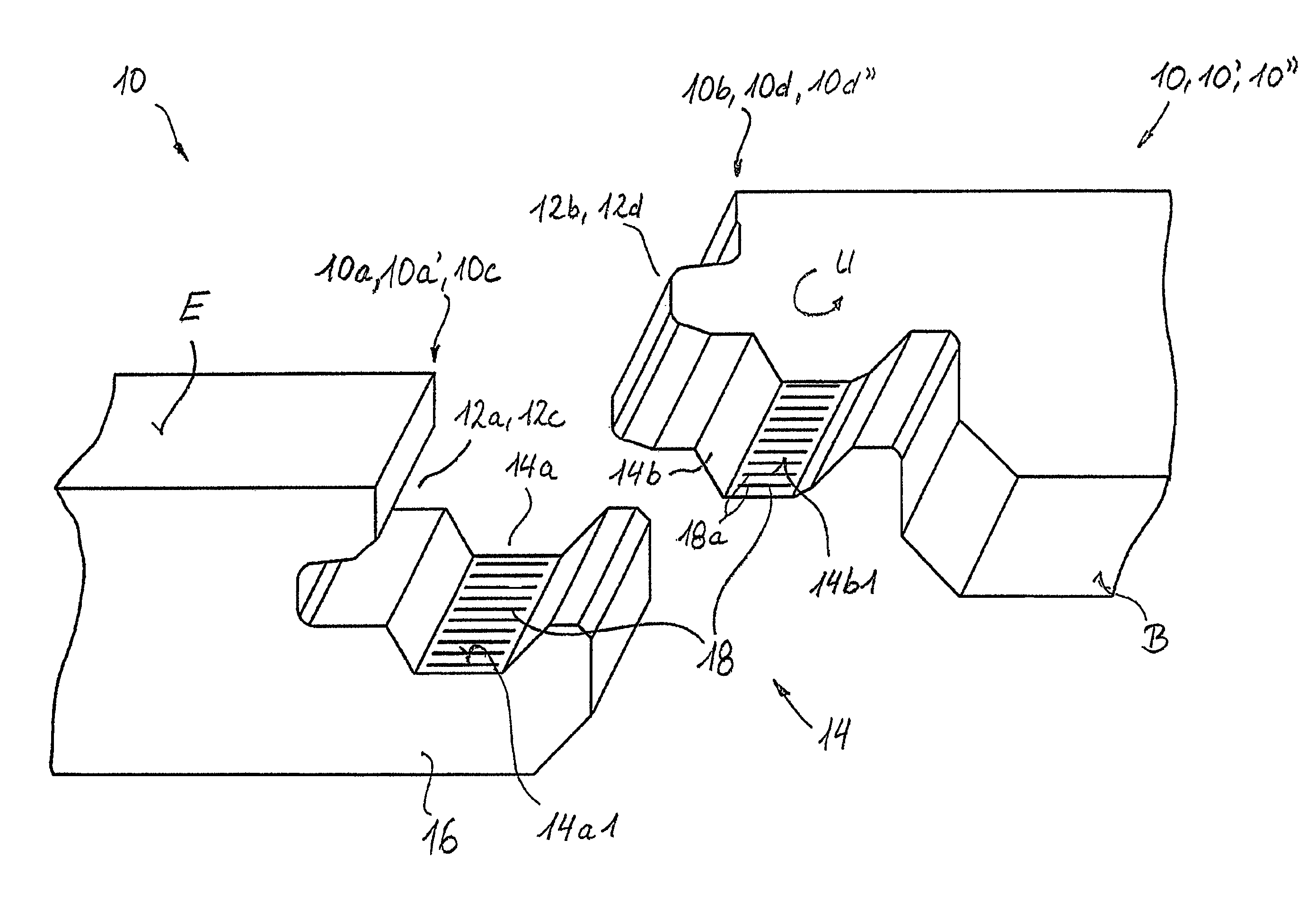
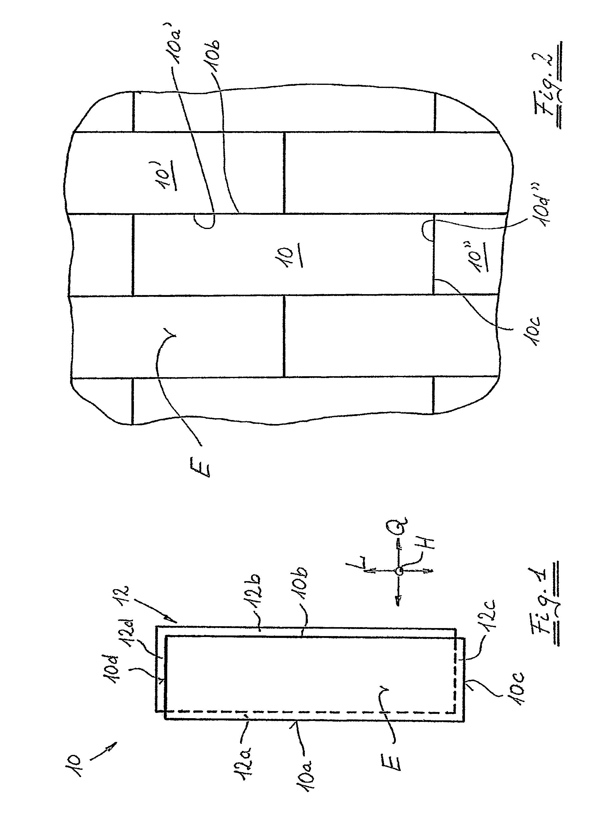
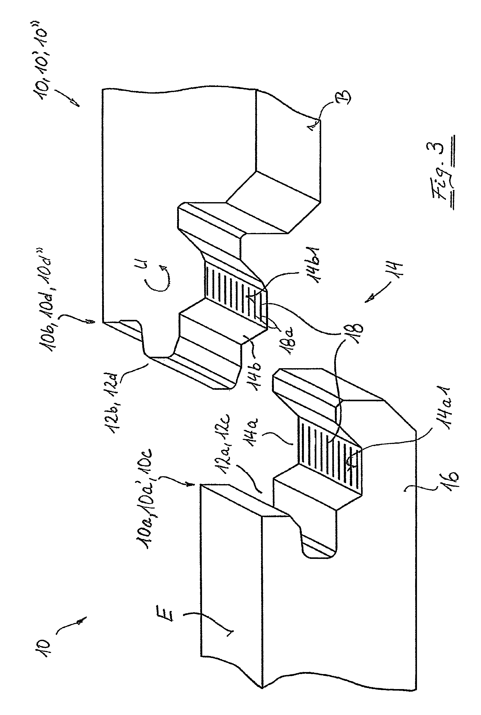
[0028]In FIG. 1, a panel according to the invention is designated in general as 10. The panel 10 is embodied as a rectangular panel and has two long sides 10a and 10b and two short sides 10c and 10d arranged respectively in pairs opposite one another. In the exemplary embodiment shown, the panel 10 is provided with a coupling mechanism both on the long sides 10a and 10b and on the short sides 10c and 10d, wherein the coupling mechanism serves to connect the panel 10 to adjacent panels 10′, 10″, etc., in the longitudinal direction L or in the transverse direction Q (see FIG. 2).

[0029]The coupling mechanism 12 is composed essentially in the form of a groove 12a provided on the long side 10a and a tongue 12b provided on the long side 10b, which together form the coupling mechanism on the long side. Additionally, the coupling mechanism is composed of a groove 12c provided on the short side 10c and a tongue 12d provided on the short side 10d, which together form the coupling mechanism on...


PUM


Abstract

The invention relates to a cladding panel having at least two pairs of side edges lying substantially opposite one another. The cladding panel includes a coupling mechanism structured and arranged on at least one of the at least two pairs of side edges, and including a groove and a tongue extending along respective side edges of the at least one pair. A roughening formed on at least a section of at least one of the tongue and the groove.

Description

CROSS-REFERENCE TO RELATED APPLICATIONS[0001]The present application is a U.S. National Stage of International Patent Application No. PCT / EP05 / 11988 filed Nov. 9, 2005, and claims priority under 35 U.S.C. §119 of German Patent Application No. 10 2004 054 368.2 filed Nov. 10, 2004.BACKGROUND OF THE INVENTION[0002]1. Field of the Invention[0003]The invention relates to a cladding panel with two pairs of side edges lying opposite to one another and, in particular, a cladding panel having at least one pair of side edges provided with a coupling device embodied essentially in the form of a groove and a tongue and extending along the respective side edge.[0004]2. Discussion of Background Information[0005]Cladding panels of this type are generally known. Reference is made by way of example to EP 1 036 244 B1.[0006]Generic panels are usually produced by essentially cuboid-shaped raw panels, i.e., raw panels, having side surfaces which are assigned to the side edges that run essentially orth...

Claims


Application Information

Patent Timeline
IPC IPC(8): E04B2/00
CPCE04F15/02E04F2201/0115E04F2201/08E04F2201/023E04F2201/0153
Inventor DUERNBERGER, GERHARD
Owner KAINDL FLOORING GMBH
Why Eureka
Try Eureka