Micromechanical device and method of manufacturing micromechanical device

a micromechanical device and micromechanical technology, applied in the direction of electrical apparatus casings/cabinets/drawers, instruments, hermetically sealed casings, etc., can solve the problem that the vibration of the mems element 104 becomes difficult to be statically determina

Inactive Publication Date: 2011-08-23
KK TOSHIBA
View PDF15 Cites 44 Cited by
  • Summary
  • Abstract
  • Description
  • Claims
  • Application Information

AI Technical Summary

Benefits of technology

[0012]The present invention has been contrived to solve the above-mentioned problems, and an object thereof is to provide a micromechanical device of a micromachine in which noise of the output signal can be reduced by making the vibration of the micromachine easily determinate.

Problems solved by technology

However, in the technique described above, there have been the following problems.
In the reduced-pressure atmosphere, the fluid resistance is small, and hence when the electrostatic force applied to the MEMS element of the spring structure is removed, vibration of the MEMS element 104 becomes difficult to be statically determinate.
Thus, when heat is applied to the devices in the assembly process after the sealing film formation, there is the possibility of the sealing body and the substrate between the sealing films, or the sealing films being peeled off each other.

Method used


Image

  • Micromechanical device and method of manufacturing micromechanical device
  • Micromechanical device and method of manufacturing micromechanical device
  • Micromechanical device and method of manufacturing micromechanical device

Examples


second embodiment

[0072]Next, the configuration of a micromechanical device 2 according to a second embodiment of the present invention will be described below with reference to FIG. 13. Incidentally, in the figures, the configuration is schematically shown by appropriately enlarging, reducing, and omitting the configuration. This embodiment is identical with the first embodiment described above except that a wide section 20b, and a constriction section 20f are formed in a close adhesion section 20a, and hence a detailed description thereof will be omitted.

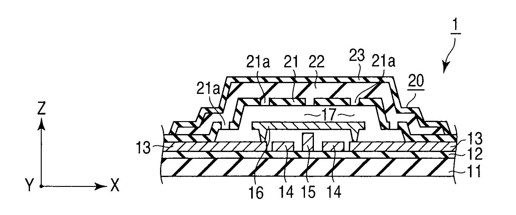
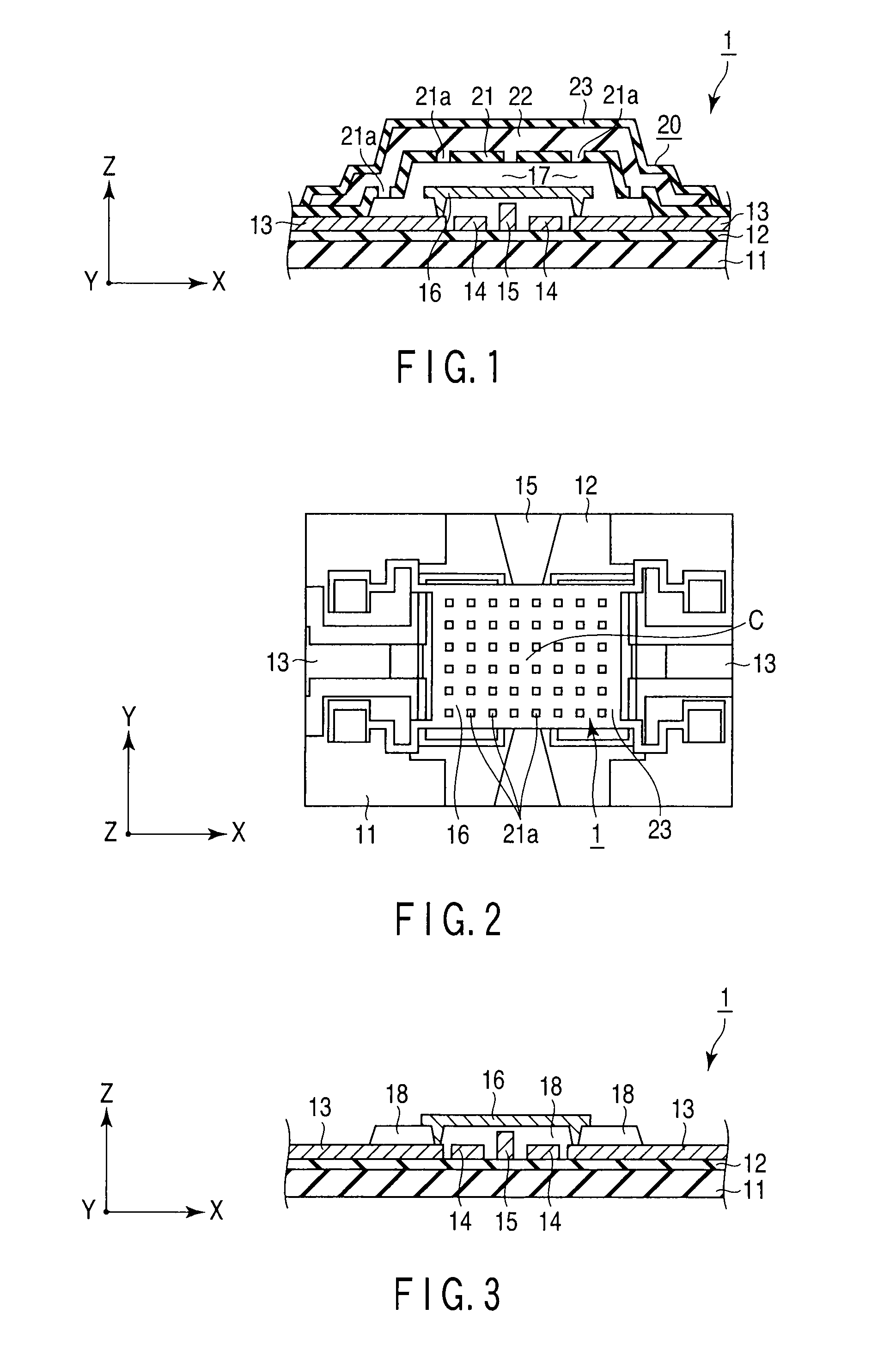
[0073]FIG. 13 shows a case where a separate sealing body 20 is formed on each of two micromechanical devices 1 arranged side by side on a substrate 11, and a hollow section 17 is formed inside each device 1 to thereby seal a MEMS element 16 therein.

[0074]Each of two sealing structures 20 constituting the hollow sections 17 includes an inner inorganic sealing film 21 formed on the substrate 11, an organic sealing film 22, and an outer inorganic seal...

third embodiment

[0086]Next, the configuration of a micromechanical device 3 according to a third embodiment of the present invention will be described below with reference to FIGS. 15 to 18. Incidentally, in the figures, the configuration is schematically shown by appropriately enlarging, reducing, and omitting the configuration. This embodiment is identical with the first embodiment described above except for the fact that an outer peripheral wall section 22a of an organic sealing film 22 constituting the sealing body 20 is formed thin, and hence a detailed description thereof will be omitted.

[0087]A two-stage sealing structure 20 constituting a hollow section 17 includes an inner inorganic sealing film 21 formed on a substrate 11, an organic sealing film 22, and an outer inorganic sealing film 23 positioned outside, and having low moisture permeability. The external shape of the sealing body 20 forms an octagonal shape long in one direction in a plan view.

[0088]The inner inorganic sealing film 21...


PUM

PropertyMeasurementUnit
thicknessaaaaaaaaaa
thicknessaaaaaaaaaa
thicknessaaaaaaaaaa

Abstract

A micromechanical device according to an aspect of the present invention includes, a substrate, a micromachine which is mounted on the substrate, is provided with a mechanism deformed by a function of an electric field, and changes the electrical characteristics concomitantly with the deformation, an inner inorganic sealing film which contains an inorganic material, is provided on a principal surface of the substrate, covers the micromachine through a hollow section containing a gaseous body therein, and is provided with opening shape sections allowing the hollow section to communicate with the outside, an organic sealing film which contains an organic material, is formed on the inner inorganic sealing film, and blocks up the opening shape sections, and an outer inorganic sealing film which contains an inorganic material with lower moisture permeability than the organic material, is formed on the organic sealing film, and covers the organic sealing film.

Description

CROSS-REFERENCE TO RELATED APPLICATIONS[0001]This application is based upon and claims the benefit of priority from prior Japanese Patent Applications No. 2007-274291, filed Oct. 22, 2007; and No. 2008-227997, filed Sep. 5, 2008, the entire contents of both of which are incorporated herein by reference.BACKGROUND OF THE INVENTION[0002]1. Field of the Invention[0003]The present invention relates to a micromechanical device of a micromachine such as packaging of a minute electromechanical component, and a method of manufacturing a micromechanical device.[0004]2. Description of the Related Art[0005]As an example of a micromechanical device shown in, for example, Jpn. Pat. Appln. KOKAI Publication No. 2005-207959, and U.S. Pat. No. 7,008,812B1, a micro-electromechanical system (MEMS) 101 in which a MEMS element 104 as a micromachine having a motion is mounted on a substrate 102, and is sealed in a hollow state as shown in FIGS. 10 to 12 are known.[0006]The MEMS 101 is constituted of a s...

Claims


Application Information

Patent Timeline
Patent Type & Authority Patents(United States)
IPC IPC(8): H01L29/84
CPCB81B3/0078B81C1/00293H03H9/00Y10T29/49002B81C2203/0145B81C2203/0136H03H9/1057B81B7/00B81C1/00
Inventor MIYAGI, TAKESHIINOUE, MICHINOBUOBATA, SUSUMUSUGIZAKI, YOSHIAKI
Owner KK TOSHIBA
Why Eureka
Try Eureka