
Methods for channel estimation in the presence of transmit beamforming

a beamforming and channel technology, applied in diversity/multi-antenna systems, amplitude demodulation, baseband system details, etc., can solve the problems of not being able to directly apply estimates as channel estimates for dpch channels, and not being suited to logical channel cpich transmission, etc., to achieve computation saving

Inactive Publication Date: 2011-08-23
TELEFON AB LM ERICSSON (PUBL)
View PDF5 Cites 0 Cited by
  • Summary
  • Abstract
  • Description
  • Claims
  • Application Information

AI Technical Summary

Benefits of technology

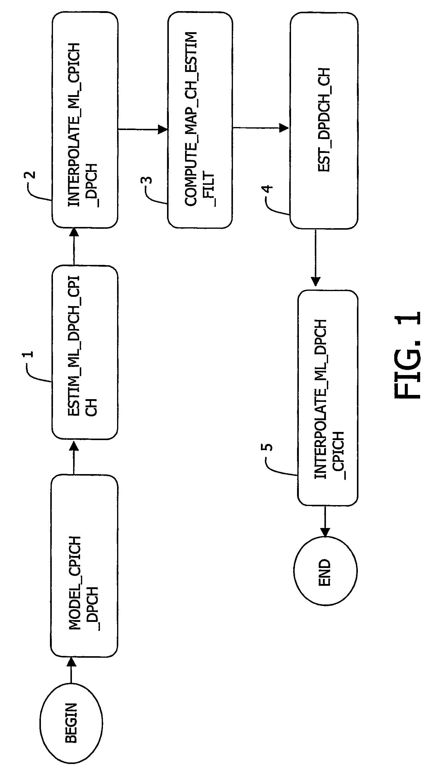
[0006]Accordingly, it is an object of the invention to provide a method for DPDCH channel estimation in the presence of transmit beamforming optimally exploiting all information available from the logical channels DPCH and CPICH, while limiting computational complexity, and an associated estimator implementing said method.
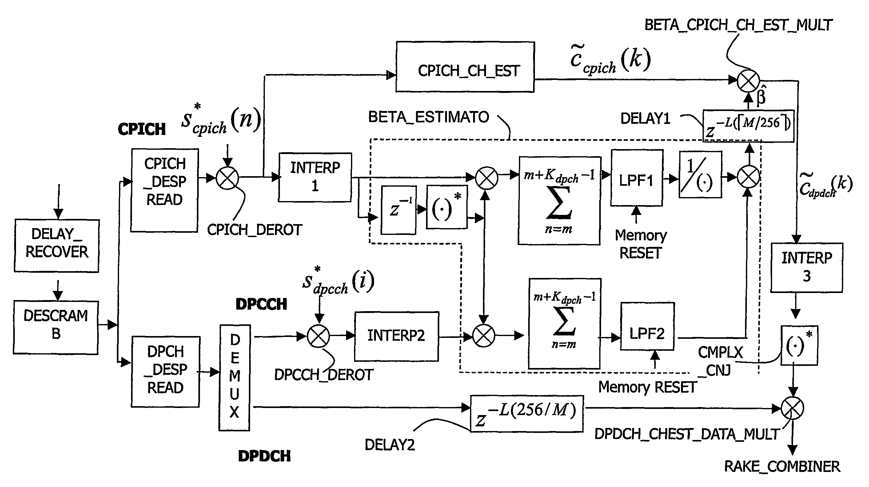
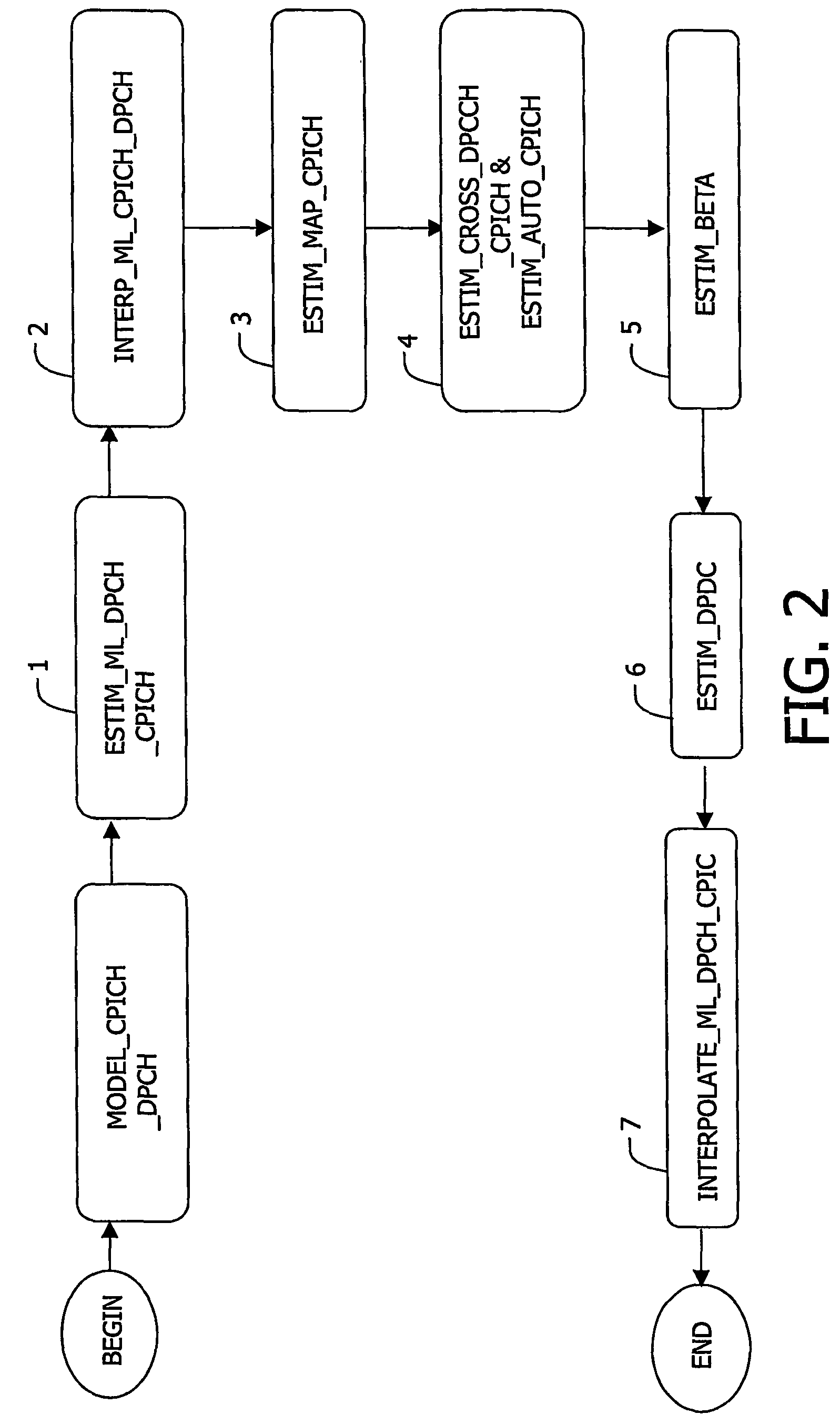
[0008]As we will see in detail further on, this method enables the UE receiver to cope with transmit beamforming applied to DPCH transmission by jointly exploiting the CPICH and DPCH logical channels information available at the UE. The first embodiment of the method optimally exploits this information according to the maximum-a-posteriori criterion, which is well known to the person skilled in the art, to estimate the DPDCH propagation channel multipath coefficients as described above. We shall show that in the presence of transmit beamforming, each multipath component coefficient of the DPCH channel differs from the corresponding multipath component coefficient of the CPICH channel by an unknown complex scale factor already referred to as beamforming complex factor. The second embodiment of the method provides an estimate of that beamforming complex factor. Then an estimate of the multipath component coefficient of the DPDCH propagation channel is built by multiplying each multipath component coefficient estimate of the CPICH channel by the related complex scale factor estimate. In this way a considerable computation saving is possible with respect to the first method. Moreover, the use of the CPICH channel estimates also allows to continuously track the channel variations with time due to the Doppler spread generated by the motion of the UE, thanks to the continuous provision of known pilot symbols of said CPICH logical channel.

Problems solved by technology

While transmit beamforming is to be employed for the transmission of the logical channel DPCH, it is not suited for the logical channel CPICH transmission that is to be uniformly broadcast in time and space (i.e. in all directions) to all users.
Unfortunately, when transmit beamforming is applied, the known pilots of the CPICH logical channel yet provide estimates for the CPICH channel, but those estimates cannot be directly applied as channel estimates for the DPCH channel that is different from the CPICH channel.

Method used


Image

  • Methods for channel estimation in the presence of transmit beamforming
  • Methods for channel estimation in the presence of transmit beamforming
  • Methods for channel estimation in the presence of transmit beamforming

Examples


Embodiment Construction

1. Introduction

[0014]In the following description, functions or constructions well-known to a person of ordinary skill in the art are not described in detail since they would unnecessarily obscure the invention.

[0015]The present invention relates to a method and embodiments for the estimation of the propagation channel in a communication system when information data are transmitted through a beamforming system. Said methods are particularly suitable for implementation in a RAKE receiver within the LTMTS standard when information data are transmitted from a base station BS to user equipment UE, here a mobile phone.

[0016]The UMTS standard provides two logical channels for the downlink communication: a first channel denoted common pilot channel (CPICH) consisting of a continuous sequence of known pilot symbols and a second logical channel denoted dedicatedphysical channel (DPCH). Said second logical channel DPCH consists of a first logical sub-channel denoted dedicated physical data ch...


PUM


Abstract

The present invention relates to a method for estimating a propagation channel in the presence of transmit beam-forming within a receiver, accounting for the structure of two logical channels referred as to a common channel and a dedicated physical channel (CPICH, DPCH) and based on a common structure of corresponding propagation channels, said DPCH channel comprising two sub-channels (DPDCH, DPCCH), said propagation channels being modeled as a linear superposition of a finite number of discrete multipath components following an uncorrelated-scattering wide-sense stationary model, a multipath component being characterized by a time-varying multipath complex coefficient and a delay. Use: RAKE Receiver.

Description

FIELD OF THE INVENTION[0001]The present invention relates to a method for estimating a propagation channel in the presence of transmit beamforming. It further relates to an estimator implementing said method.[0002]Said method is suited to be used in particular within the UMTS standard and especially within a conventional RAKE receiver.BACKGROUND OF THE INVENTION[0003]A UMTS communication system, defined in the UTMTS standard (see the “3GPP Technical Specifications, Rel. 99”), at the 3GPP website under specifications, incorporated herein by reference, comprises at least a base station (BS) and a mobile phone terminal, referred to as user equipment (UE) throughout the document. Both the BS and the UE includes a transmitter and a receiver. The BS sends signals by means of the BS transmitter to the UE receiver in the downlink. The UE sends signals by means of the UE transmitter to the BS receiver in the uplink. In uplink and downlink communication both the UE and BS map the data to be t...

Claims


Application Information

Patent Timeline
Patent Type & Authority Patents(United States)
IPC IPC(8): H04B7/02H04B1/707H04B1/712H04L25/02
CPCH04L25/0204H04L25/0232
Inventor MONTALBANO, GIUSEPPE
Owner TELEFON AB LM ERICSSON (PUBL)
Learn More