Image forming apparatus

a technology of image forming apparatus and forming head, which is applied in the direction of electrographic process apparatus, optics, instruments, etc., can solve the problems of difficult to effectively use the internal space of the image forming apparatus, difficulty in providing stable and accurate positioning between the led head and the photosensitive element, and difficulty in providing stable and accurate positioning. , to achieve the effect of stably and reliably providing the developer, high positioning accuracy, and easy to perform the accurate positioning of the exposure member

Active Publication Date: 2011-08-23
BROTHER KOGYO KK
View PDF18 Cites 9 Cited by
  • Summary
  • Abstract
  • Description
  • Claims
  • Application Information

AI Technical Summary

Benefits of technology

[0009]In order to stably and reliably supply developer to the process cartridge, the developer cartridge is attached to the process cartridge with a relatively high positioning accuracy. Therefore, the exposure member is accurately pressed by the pressing portion of the developer cartridge toward the photosensitive element. As a result, it is possible to readily perform an accurate positioning of the exposure member relative to the photosensitive element.
[0010]Further, the moving passage (trajectory) of the exposure member can be shortened to such an extent that the pressing portion of the developer cartridge causes the exposure member to move to the photosensitive element. This makes it possible to effectively use the internal space of the image forming apparatus.
[0011]According to the present invention, since the pressing portion of the developer cartridge presses the exposure member and causes the exposure member to move from the second position to the first position, an accurate positioning of the exposure member relative to the photosensitive element is readily performed while the internal space of the image forming apparatus can be used effectively.

Problems solved by technology

Therefore, the top cover does not provide a stable and accurate pressing force, which may result in a difficulty in accurate positioning between the LED head and the photosensitive element.
Further, it is difficult to effectively use the internal space of the image forming apparatus in which the LED head is supported by the pivotable top cover.

Method used


Image

  • Image forming apparatus
  • Image forming apparatus
  • Image forming apparatus

Examples


Embodiment Construction

[0025]One preferred embodiment of the present invention will be described in detail with reference to the attached drawings.

Exterior of Printer

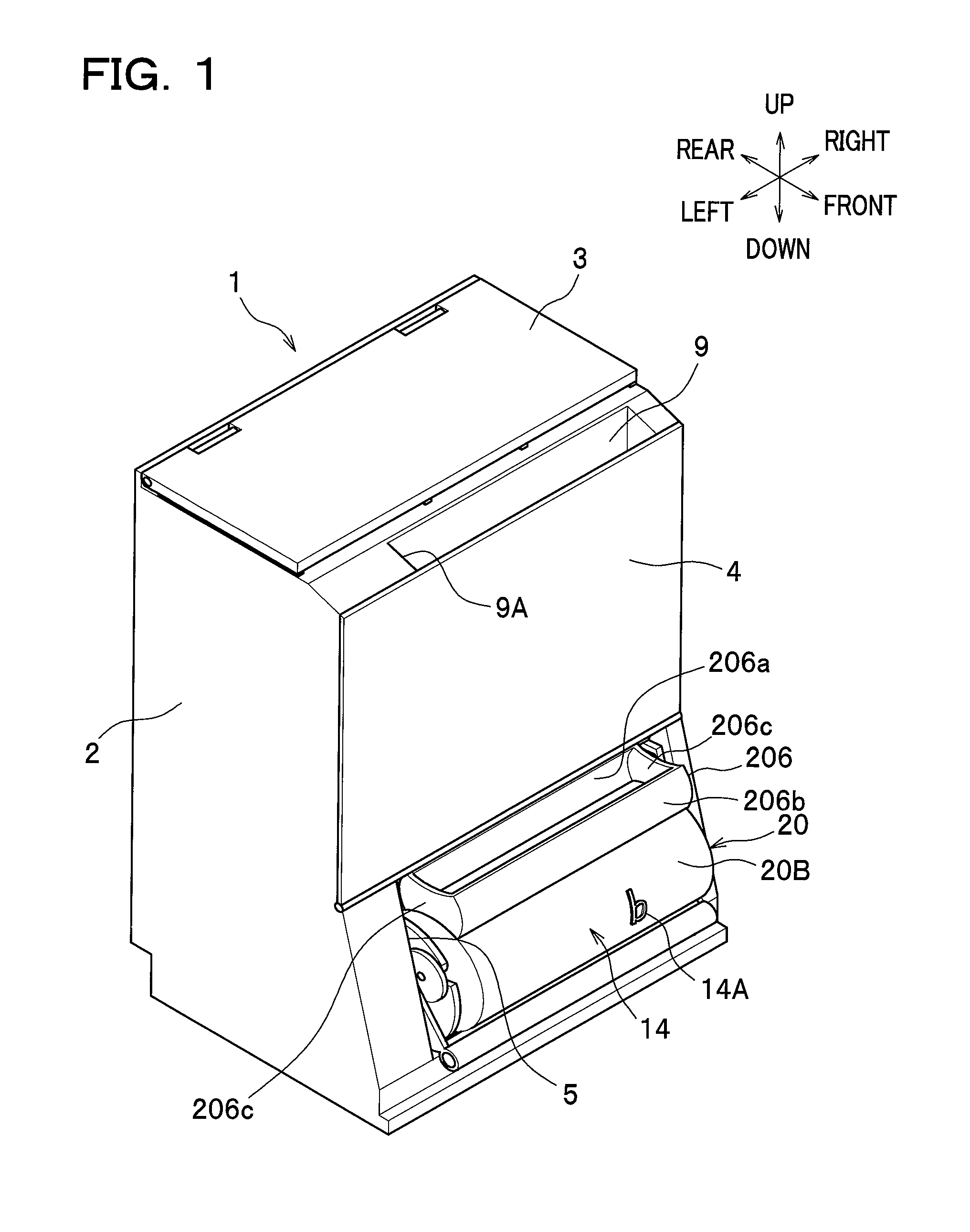
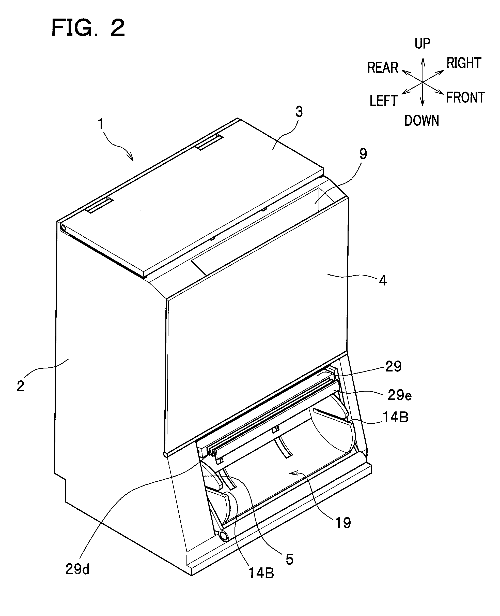
[0026]As seen in FIGS. 1 and 2, an image forming apparatus according to one embodiment of the present invention is provided as an upright-type printer 1, which has a relatively short length in the front-rear direction compared to the right-and-left direction and the height of which is tall.

[0027]The printer 1 has a main body casing 2. A top cover 3 is provided at an upper part of the main body casing 2, and a front cover 4 is provided at a front upper part of the main body casing 2. Provided at a front lower part of the main body casing 2 is an attachment opening 5, through which the attachment and detachment of a process cartridge 14 and a toner cartridge 20 are performed. The process cartridge 14 constitutes an image forming unit 8 to be described later, and the toner cartridge 20 is an example of a developer cartridge. In this preferred em...


PUM


Abstract

An image forming apparatus includes: a process unit including a photosensitive element; an exposure member exposing the photosensitive element to light to form an electrostatic latent image on the photosensitive element; a main body casing accommodating the process unit and the exposure member; and a developer cartridge supplying developer to the process unit. The developer cartridge is attachable to and removable from the process unit. In this image forming apparatus, the exposure member is positioned between the photosensitive element and the developer cartridge so as to be attached and movable between a first position in which the photosensitive element is exposed to light by the exposure member and a second position in which the exposure member is away from the photosensitive element. Further, the developer cartridge has a pressing portion for pressing the exposure member toward the first position with the developer cartridge being attached to the main body casing.

Description

CROSS REFERENCE TO RELATED APPLICATIONS[0001]This application claims the foreign priority benefit under Title 35, United States Code, §119(a)-(d) of Japanese Patent Application No. 2007-144765 filed on May 31, 2007 in the Japan Patent Office, the disclosure of which is herein incorporated by reference in its entirety.BACKGROUND OF THE INVENTION[0002]The present invention relates to an image forming apparatus equipped with an exposure member, which is movable toward and away from a photosensitive element.[0003]Generally, in a known image forming apparatus, a photosensitive drum (photosensitive element) is electrically charged and this electrically charged photosensitive drum is then irradiated with light so that the electric potential of the irradiated area lowers to form an electrostatic latent image on the photosensitive drum. Thereafter, developer is supplied onto this latent image to form a developer image, which is then transferred onto a paper so that a predetermined image is f...

Claims


Application Information

Patent Timeline
Patent Type & Authority Patents(United States)
IPC IPC(8): G03G21/16
CPCG03G15/326G03G21/1839G03G21/1604G03G15/0855G03G15/04054G03G15/0865G03G15/0886G03G15/0893G03G21/1647G03G2221/1636G03G2221/1654
Inventor SATO, SHOUGO
Owner BROTHER KOGYO KK
Why Eureka
Try Eureka