Multi-layer building insulation and wallboard sheet with multi-layer insulation

a technology of building insulation and multi-layer insulation, which is applied in the field of multi-layer building insulation and wallboard sheets with multi-layer insulation, can solve the problems of building after construction, large dimension of typical framing materials, and substantial cost of materials over fiberglass blankets or cellulos

Inactive Publication Date: 2011-09-06
HETTRICH HANSL
View PDF20 Cites 7 Cited by
  • Summary
  • Abstract
  • Description
  • Claims
  • Application Information

AI Technical Summary

Problems solved by technology

These requirements are approaching a point where typical framing materials, from which structures are usually constructed, will not be large enough in dimension to contain the increased thicknesses of insulation—typically inexpensive thermal insulation made of fiberglass blankets or loose-packed cellulose, for example.
Construction professionals who are accustomed to designing and building wood structures would be greatly disadvantaged by such changes, and the economic impact of such changes on many tens of thousands of people will likely not be insubstantial.
However, such materials are substantially more expensive than fiberglass blankets or cellulose.
Even structures that were built after the institution of thermal efficiency requirements were not built to today's efficiency standards.
Effectively retrofitting existing buildings with traditional insulating materials is usually a costly endeavor.
Moreover, the absorption of moisture by fiberglass and cellulose insulation materials from interior or exterior sources has the effect of reducing the effective “R” values of the insulation, as compared with R-values of the same material when dry.
If sufficiently severe, this phenomenon can even result in an R value that is less than air (i.e., a situation worse than no insulation at all).
It is likely, therefore, that the insulation of structures currently insulated with fibrous insulation have not completely maintained their thermal efficiency.

Method used


Image

  • Multi-layer building insulation and wallboard sheet with multi-layer insulation
  • Multi-layer building insulation and wallboard sheet with multi-layer insulation

Examples


Embodiment Construction

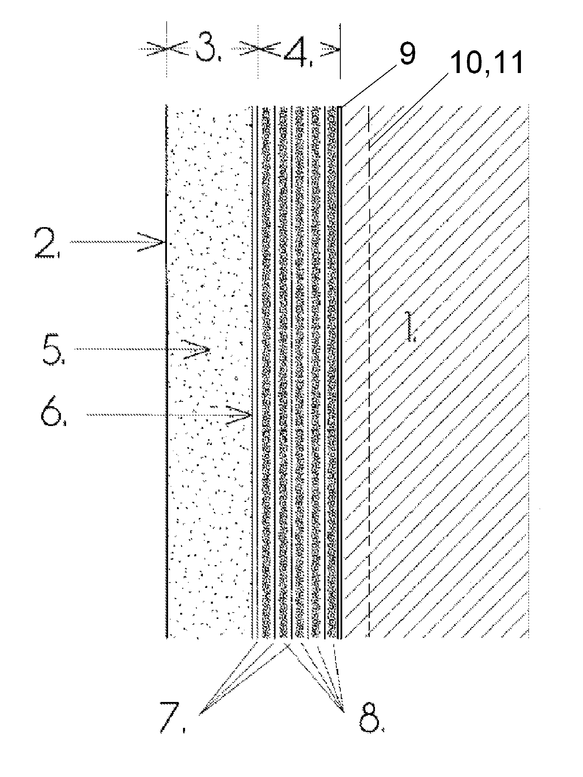
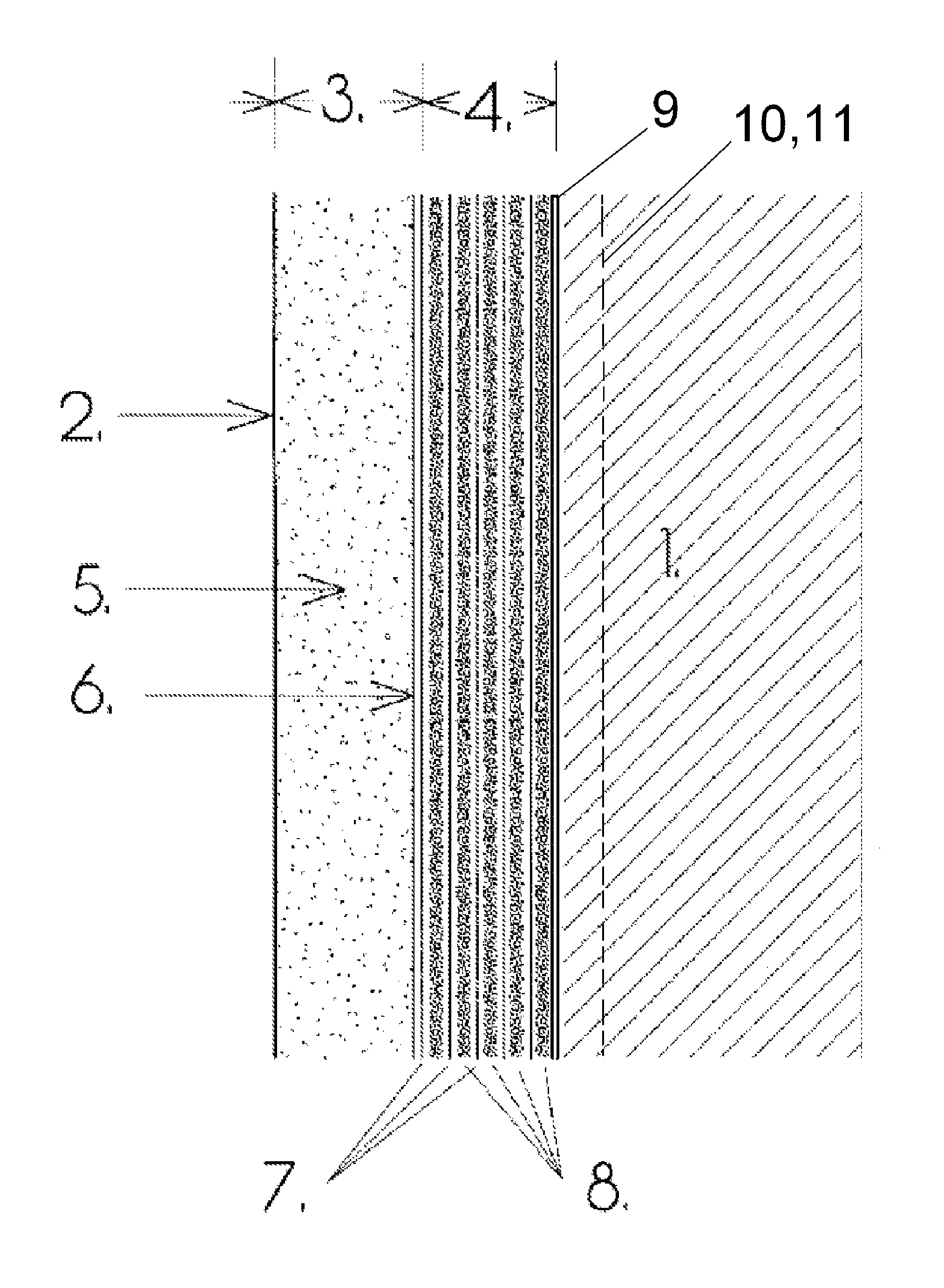
[0015]In accordance with the disclosure, a multi-layer building insulation material and a wallboard sheet with multi-layer insulation, and related manufacturing and installation methods are provided. In accordance with the disclosure, layers of membranes and air can be “sandwiched” together increase the thermal insulating value (“R” value) of a surface beyond that of a single layer of insulating material. In place of an air layer, a thin layer of foam plastic can be used as a separator between two adjacent layers or membranes. By way of further example, one or more layers of a clay aerogel can be used as an insulating layer. Such materials are known in the art and described, for example, in U.S. patent application Ser. No. 11 / 713,189, filed Mar. 2, 2007 and in U.S. patent application Ser. No. 12 / 012,248, filed Feb. 1, 2008. Each of the aforementioned patent applications is incorporated by reference herein in its entirety.

[0016]It is believed that an “R” value of about 1 can be achie...


PUM

PropertyMeasurementUnit
impermeableaaaaaaaaaa
air-impermeableaaaaaaaaaa
insulatingaaaaaaaaaa

Abstract

A multilayer insulation material is provided. The insulation material preferably includes a plurality of substantially air-impermeable material layers joined together, with at least one space being provided between a pair of adjacent material layers thereof. At least one layer of a foam material and / or aerogel material can be interposed between a pair of adjacent material layers. At least one reflective layer can be provided for inhibiting radiative heat transfer across the insulation material. In accordance with another aspect of the disclosure, a construction panel is provided, having a structural panel portion having predetermined material properties for performing a predetermined function, and a plurality of substantially air-impermeable material layers joined to the structural panel portion, at least one space being provided between a pair of adjacent material layers thereof.

Description

CROSS-REFERENCE TO RELATED APPLICATIONS[0001]This patent application claims priority to U.S. Provisional Patent Application Ser. No. 61 / 159,776, filed Mar. 12, 2009. The aforementioned patent application is incorporated by reference herein in its entirety.BACKGROUND[0002]Most buildings enclose space which must be heated and cooled for occupancy. Depending on the location of the structure on Earth and the season, the building's envelope maintains a temperature differential between the inside and the outside. The ability of the envelope to reduce the flow of heat into or out of the volume is called its thermal resistance. The greater the thermal resistance a portion of the envelope has, the less energy is required to maintain that temperature differential. In the building industry, resistance to conductive thermal loss is measured in the unit “R” (“R-value”). It is the inverse of the unit of thermal conductivity, often represented by the unit “I” (or alternatively “U” or “U-value”).[0...

Claims


Application Information

Patent Timeline
Patent Type & Authority Patents(United States)
IPC IPC(8): E04C1/00
CPCB32B5/18B32B27/32E04B1/78E04B1/80B32B2307/304B32B2315/16B32B2323/10E04B2001/7691Y02B80/14B32B13/02B32B13/06B32B13/12B32B15/10B32B21/08B32B27/065B32B27/10B32B2255/10B32B2255/205B32B2262/101B32B2272/00B32B2307/306B32B2307/416B32B2307/7145B32B2307/7242B32B2419/00B32B2419/06B32B2607/00Y02A30/24Y02B80/10Y10T428/249953
Inventor POLLACK, ROBERT WILLIAM
Owner HETTRICH HANSL
Why Eureka
Try Eureka