Radio frequency transparent thermal window

a technology of thermal window and radio frequency, applied in the field of radio frequency transparent thermal window, to achieve the effect of lowering the temperature of the cooling elemen

Active Publication Date: 2013-05-23
THE AEROSPACE CORPORATION
View PDF7 Cites 14 Cited by
  • Summary
  • Abstract
  • Description
  • Claims
  • Application Information

AI Technical Summary

Problems solved by technology

However, vacuum and thermal chambers typically are made of metal or other conductive substances, and are found to interfere with radio signals passing between the device under test and the reciprocal radio transmitter-receiver outside the chamber when testing the performance of a device with respect to transmission and reception of radio frequency signals via antennae.

Method used


Image

  • Radio frequency transparent thermal window
  • Radio frequency transparent thermal window
  • Radio frequency transparent thermal window

Examples


Embodiment Construction

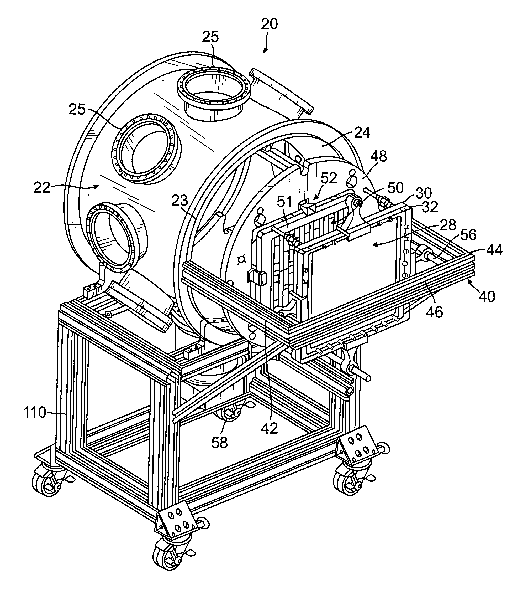
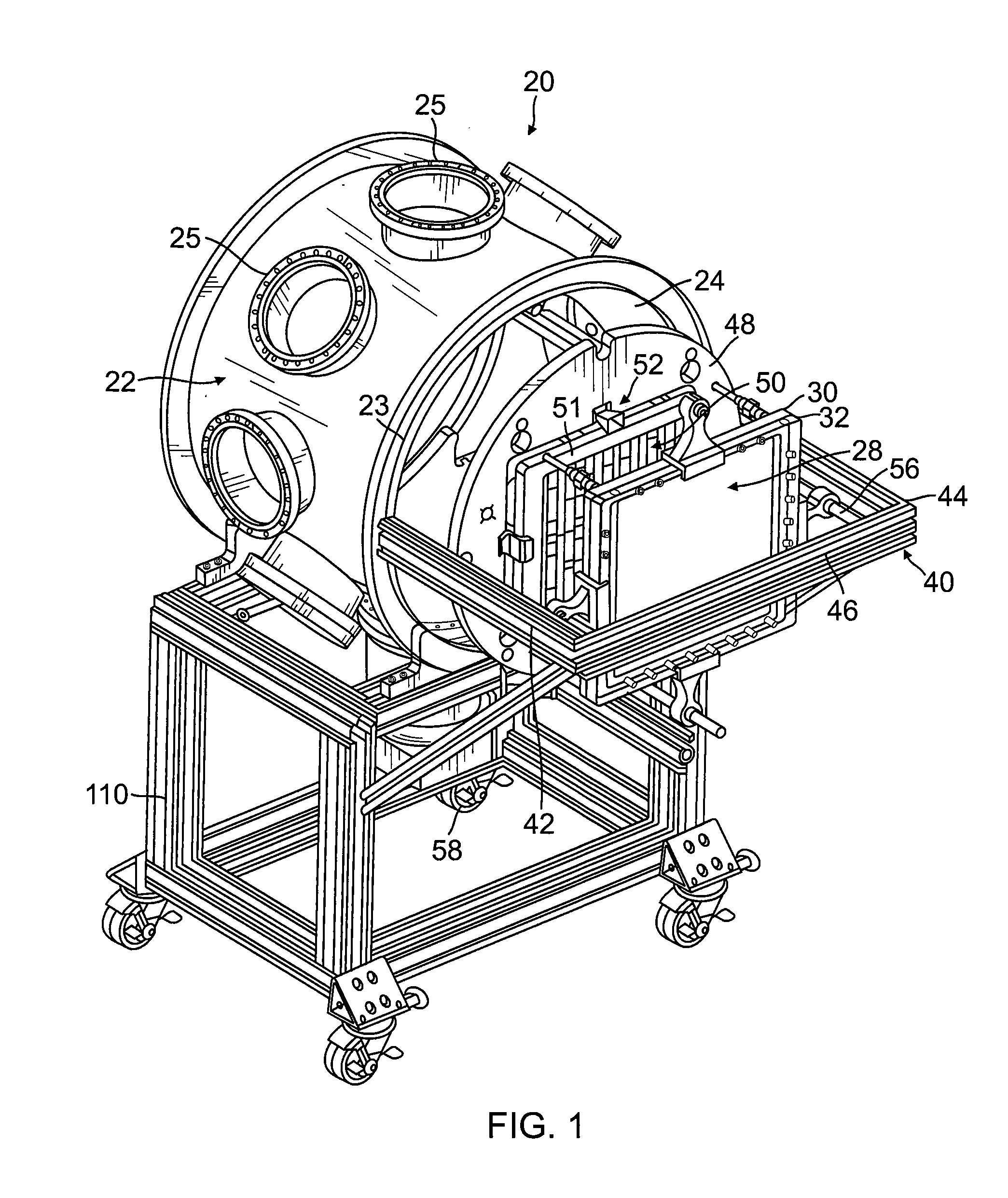
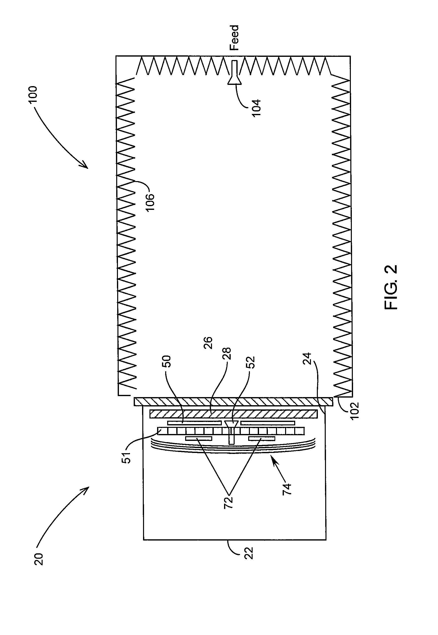
[0021]With reference to the drawings, there is described a preferred embodiment of a test chamber of a system and method for testing electronic devices that will be used in outer space, the chamber being configured firstly to simulate temperature and pressure conditions found in space, and secondly to permit substantially unimpeded radio communication from outside the chamber with the device under test inside the chamber.

[0022]Chamber and Components

[0023]In a first aspect, and with reference to FIGS. 1 and 2, the test chamber 20 of the preferred embodiment defines a housing 22, configured to be evacuated to a space-like pressure. Preferably, the housing is configured generally in the shape of a cylinder, and may be formed from metal, such as stainless steel, and is further configured to receive within its interior electronic components that will be subjected to test protocols which simulate use requirements in space. In preferred embodiments, the cylinder may be between 2.5 feet and...


PUM

PropertyMeasurementUnit
temperatureaaaaaaaaaa
diameteraaaaaaaaaa
diameteraaaaaaaaaa

Abstract

A radio-frequency transparent window having internal conduits for the passage of cooling fluid is configured for simulating a highly uniform thermal environment for testing a device intended for use in space. The device to be tested is placed within a chamber in which a vacuum condition is maintained by a radio-frequency transparent pressure window under a pressure seal. Within the chamber, the thermal window is positioned adjacent, but not in contact with, the pressure window. A radio frequency signal is capable of passing directly through both the thermal window and the pressure window to permit communication with the device being tested within the housing. The thermal window is not in contact with the device so there in no conduction of heat from the device. Radiant heat transfer may occur from the device to the thermal window.

Description

FEDERALLY FUNDED RESEARCH[0001]This invention was made with government support under Contract No. FA8802-09-C-0001 awarded by the Department of the Air Force. The government has certain rights in the invention.BACKGROUND[0002]The present invention relates to methods of testing electronic components that are destined to be launched into space as part of suborbital, orbital, or remote spacecraft.[0003]Spacecraft are becoming an ever increasing component of our lives, even if in an indirect way. In addition to the manned spacecraft that are sent to the International Space Station or beyond, there are many unmanned spacecraft that are launched every year including probes sent to deep outer space and distant planets, orbiting weather satellites, orbiting global positioning satellites, and sub-orbital intercontinental missiles that may or may not have a military purpose. Such spacecraft are controlled by complex electronic components that are designed and assembled on earth, but which mus...

Claims


Application Information

Patent Timeline
Patent Type & Authority Applications(United States)
IPC IPC(8): G01N17/00
CPCG01N17/00G01N17/002B64G7/00
Inventor TOCKSTEIN, MICHAEL A.NOKES, JAMES P.OSBORN, JON V.PATEL, DHRUV N.HOPKINS, ALAN R.WILLIAMS, JOHN S.
Owner THE AEROSPACE CORPORATION
Why Eureka
Try Eureka