Cooling assembly for electronics drawer using passive fluid loop and air-cooled cover

a technology of electronics drawer and cooling assembly, which is applied in the direction of insulated conductors, power cables, cables, etc., can solve the problems of increasing device temperature, increasing power dissipation, and therefore heat production, and achieve the effect of increasing the surface area

Inactive Publication Date: 2005-11-10
IBM CORP
View PDF13 Cites 62 Cited by
  • Summary
  • Abstract
  • Description
  • Claims
  • Application Information

AI Technical Summary

Benefits of technology

[0009] The shortcomings of the prior art are overcome, and further advantages realized, by the provision of a passive liquid cooling loop and air cooled cover assembly for an electronics drawer, per the teachings of the present invention. The air cooled cover assembly provides an increased surface area from which to

Problems solved by technology

This heat should be removed from the devices in order to maintain device junction temperatures within desirable limits: failure to remove the heat thus produced results in increased device temperatures, potentially leading to thermal runaway conditions.
First, power dissipation, and therefore heat production, increases as the device operating frequencies increase.
Finally, as more and more devices are packed onto a single chip, power density (Watts/cm2) increases, resulting in the need to remove more power from a given size chip or module.
These trends have combined to create applications where it is no longer desirable to remove the heat from modern devices solely by traditional air cooling methods, such as by using traditional air cooled heat sinks.
While alternatives to air cooling are known, such as chilled water and refrigeration systems, these alternatives tend to increase both manufacturing and operational costs, and therefore tend to be applied primarily in high performance applications.
While an increase in any of these factors tends to improve the efficiency with which heat t

Method used


Image

  • Cooling assembly for electronics drawer using passive fluid loop and air-cooled cover
  • Cooling assembly for electronics drawer using passive fluid loop and air-cooled cover
  • Cooling assembly for electronics drawer using passive fluid loop and air-cooled cover

Examples


Embodiment Construction

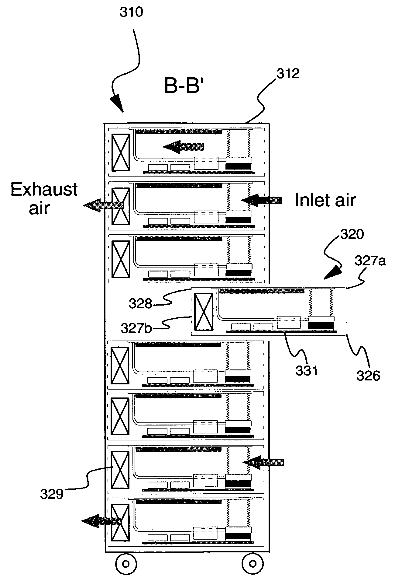
[0038] In accordance with preferred embodiments of the present invention, a passive liquid cooling loop and air cooled cover assembly for an electronics drawer is disclosed herein.

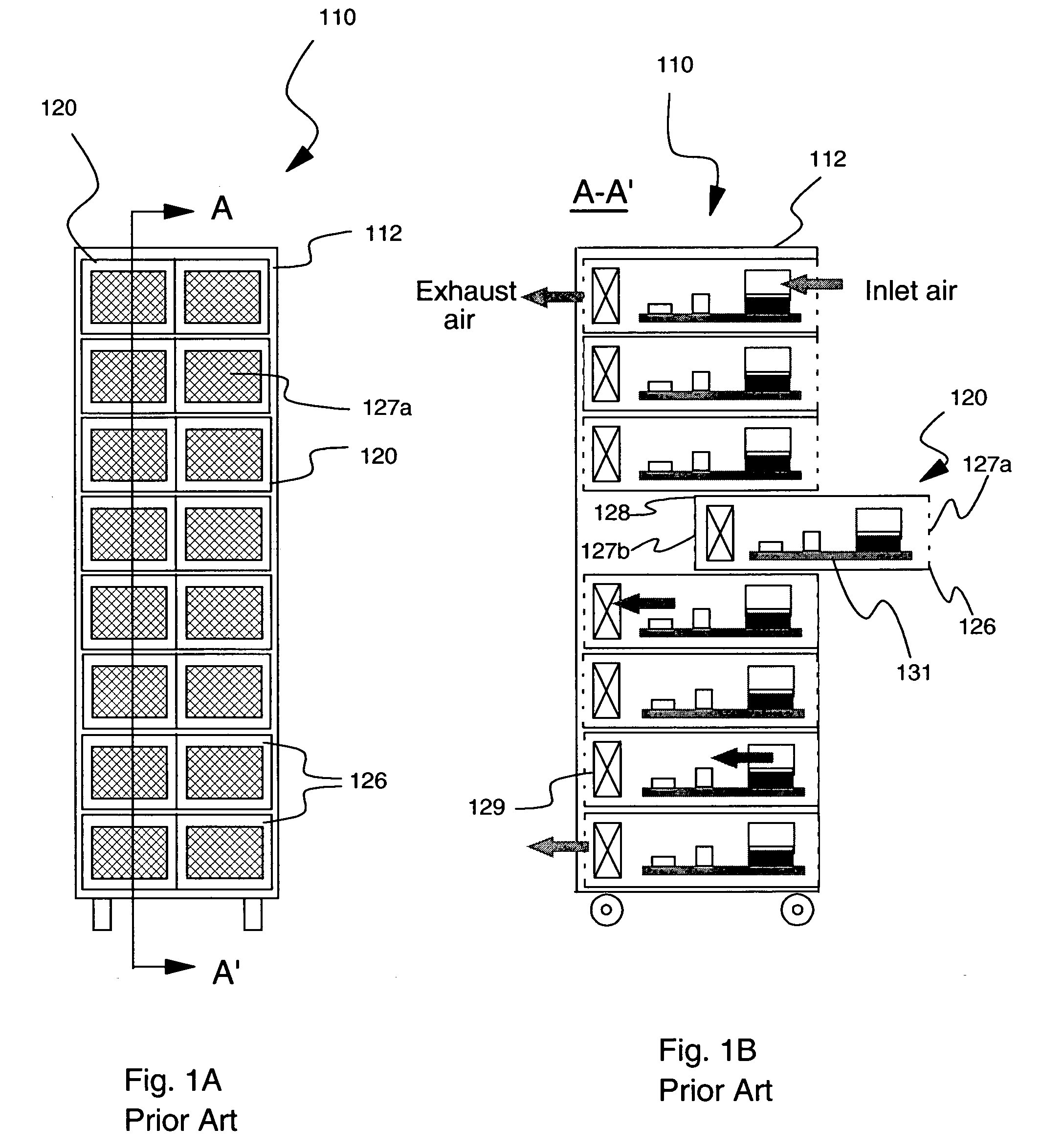
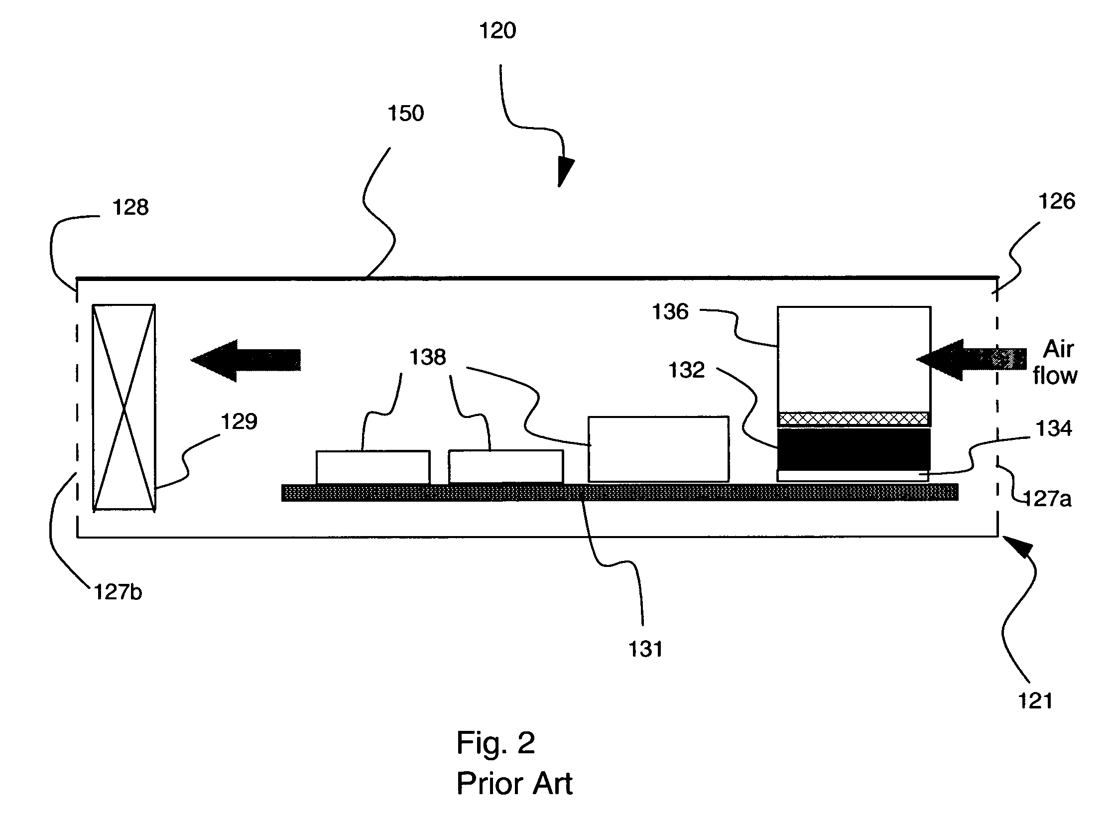
[0039]FIGS. 1A and 1B illustrate prior art electronics rack assembly 110. FIG. 1A depicts a front view, showing a two-column array of electronics drawers 120 arranged within rack frame 112. Rack frame 112 provides mechanical support for the array of drawers 120: drawers 120 are preferably mounted within rack frame 112 such that each drawer is capable of being slid forward without disturbing other drawers 120, as illustrated in FIG. 1B. Each drawer includes a front panel 126 having air inlet 127a, through which ambient air enters each drawer 120. FIG. 1B depicts a cross section of rack 110, taken along line A-A′ of FIG. 1A. As illustrated in FIG. 1B, each drawer 120 includes an air moving device, such as fan 129, mounted within drawer 120. Fan 129 causes air to flow from air inlet 127a within drawer front ...


PUM


Abstract

A cooling apparatus for electronic drawers utilizing a passive fluid cooling loop in conjunction with an air cooled drawer cover. The air cooled cover provides an increased surface area from which to transfer heat to cooling air flowing through the drawer. The increased cooling surface uses available space within the drawer, which may be other than immediately adjacent to a high power device within the drawer. The passive fluid cooling loop provides heat transfer from the high power device to the air cooled cover assembly, allowing placement of the air cooled cover assembly other than immediately adjacent to the high power device. The cooling apparatus is easily disengaged from the electronics drawer, providing access to devices within the drawer.

Description

FIELD OF THE INVENTION [0001] The present invention relates in general to cooling electronics systems. In particular, the present invention relates to enhanced cooling of one or more high power electronic components within an air cooled electronics drawer. BACKGROUND OF THE INVENTION [0002] As is known, operating electronic devices produce heat. This heat should be removed from the devices in order to maintain device junction temperatures within desirable limits: failure to remove the heat thus produced results in increased device temperatures, potentially leading to thermal runaway conditions. Several trends in the electronics industry have combined to increase the importance of thermal management, including heat removal for electronic devices, including technologies where thermal management has traditionally been less of a concern, such as CMOS. In particular, the need for faster and more densely packed circuits has had a direct impact on the importance of thermal management. Firs...

Claims


Application Information

Patent Timeline
IPC IPC(8): H05K7/20
CPCH05K7/20809H05K7/20727
Inventor CHU, RICHARD C.ELLSWORTH, MICHAEL J. JR.SCHMIDT, ROGER R.SIMONS, ROBERT E.
Owner IBM CORP
Why Eureka
Try Eureka