Refrigeration system mounted within a deck

a technology of refrigeration system and deck, which is applied in the direction of domestic cooling apparatus, lighting and heating apparatus, support, etc., can solve the problems of limited efficiency of heat exchanger, and achieve the effect of maximizing cabinet interior space and high efficiency

Active Publication Date: 2011-09-06
THERMO FISHER SCI ASHEVILLE
View PDF65 Cites 9 Cited by
  • Summary
  • Abstract
  • Description
  • Claims
  • Application Information

AI Technical Summary

Benefits of technology

[0015]Accordingly, the system and related methods described herein, by having a heat exchanger in the deck of the freezer, allows the positioning of adequate quantities of insulation around the heat exchanger, thereby attaining higher efficiencies than observed with conventional ultra-low temperature freezers. Moreover, having the heat exchanger in the deck of the freezer allows for maximization of the cabinet interior space above the deck.

Problems solved by technology

Heat exchangers of this type, however, typically occupy large spaces to permit the desired type of heat exchange between the refrigerants.
The space and orientation requirements for these heat exchangers force designers to place them alongside or behind the walls of the inner freezer chamber, in front of the outer freezer cabinet, typically taking up valuable cooling / storage space thus not available for cooling.
In addition to the above, the attainable efficiency of these heat exchangers is limited by the relatively small amount of insulation that can be arranged around them between the walls of the inner freezer chamber and the outer freezer cabinet.

Method used


Image

  • Refrigeration system mounted within a deck
  • Refrigeration system mounted within a deck
  • Refrigeration system mounted within a deck

Examples


Embodiment Construction

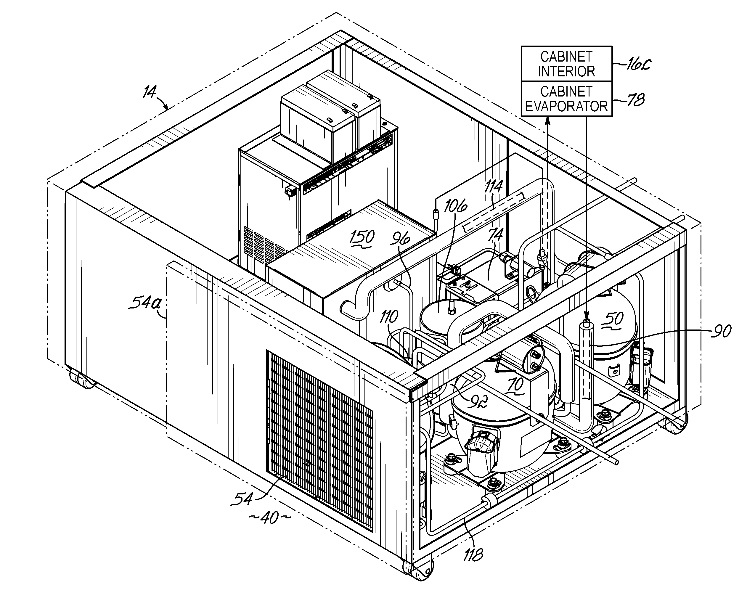
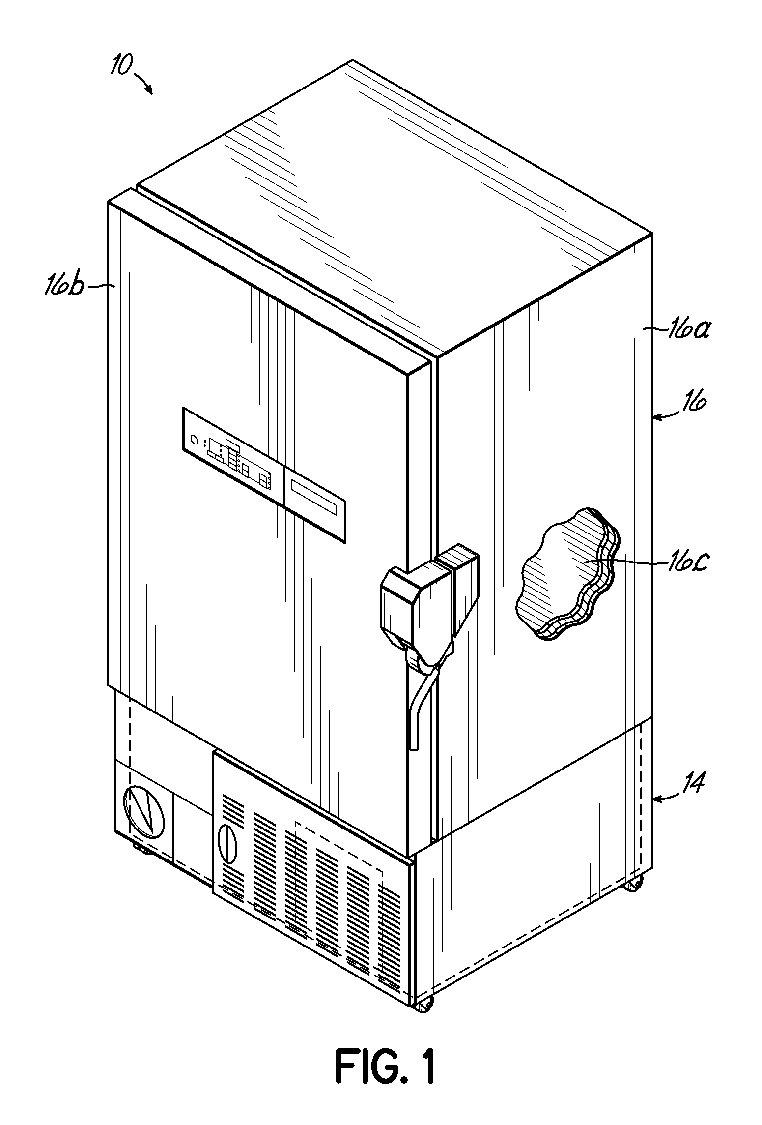
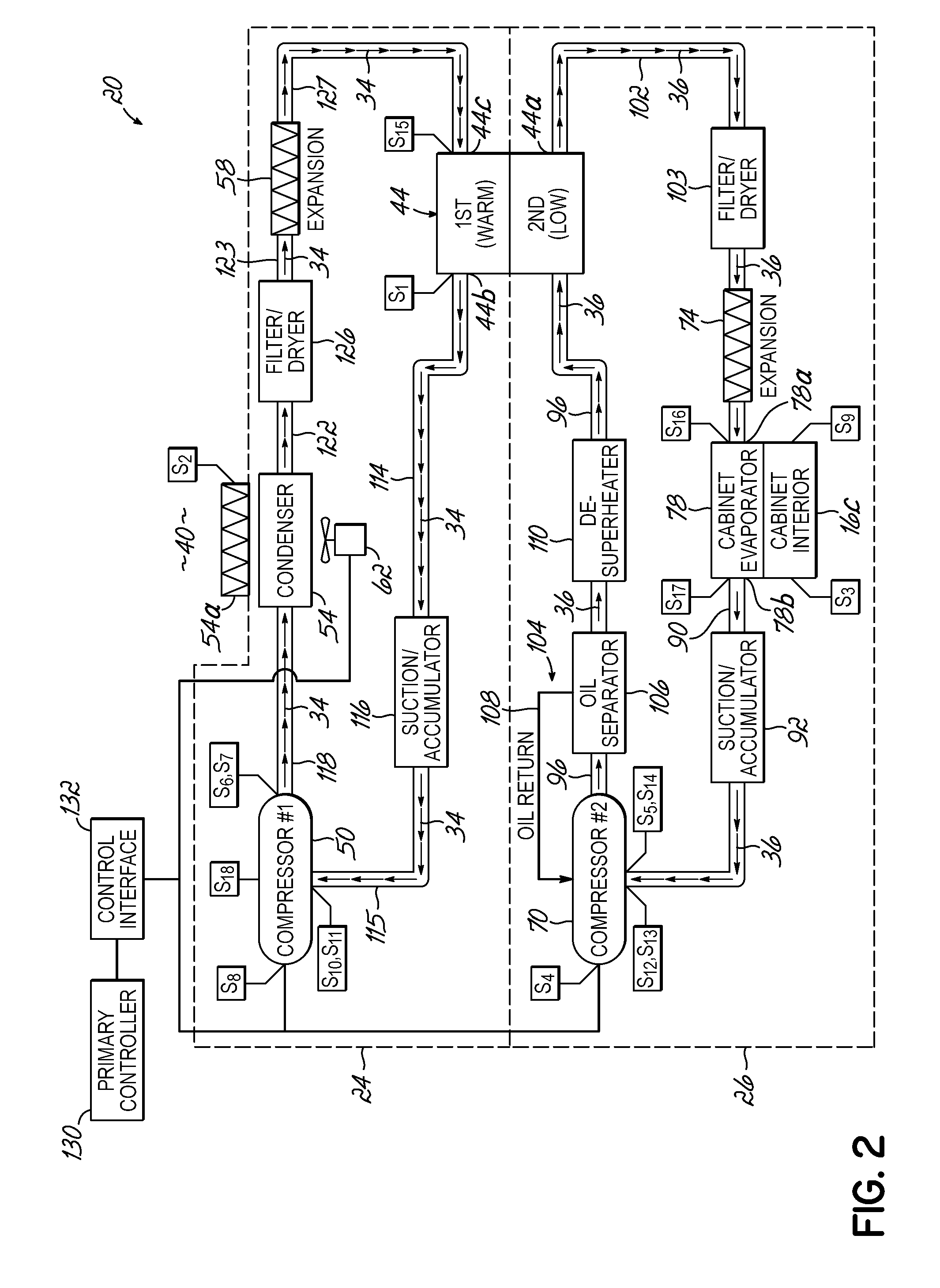
[0023]With reference to the figures, and more specifically to FIG. 1, an exemplary refrigeration unit according to one embodiment of the present invention is illustrated. The unit of FIG. 1 is in the form of an ultra-low temperature freezer (“ULT”) 10 having a deck 14 that supports a cabinet 16 thereabove, for storing items that require cooling to temperatures of about −80° C. or lower, for example. The cabinet 16, in turn, includes a cabinet housing 16a and a door 16b providing access into an interior 16c of the cabinet 16. The deck 14 supports one or more components that jointly define a two-stage cascade refrigeration system 20 (FIG. 2) that thermally interacts with cabinet 16 to cool the interior 16c thereof. As used herein, the term “deck” refers to the structural assembly or framework that is located beneath and supports the cabinet 16. An exemplary refrigeration system similar to system 20 is described in U.S. patent application Ser. No. 12 / 570,348, entitled REFRIGERATION SYS...


PUM


Abstract

A refrigeration system is provided for use with an ultra-low temperature freezer having a deck and a refrigerated cabinet supported above the deck. The system has a first refrigeration stage and a second refrigeration stage. The first stage defines a first fluid circuit for circulating a first refrigerant. The first stage has a first compressor, a condenser and a first expansion device that is in fluid communication with the first fluid circuit. The second stage defines a second fluid circuit for circulating a second refrigerant. The second stage has a second compressor, a second expansion device and an evaporator that is in fluid communication with the second fluid circuit. The system includes an insulated enclosure supported within the deck and a split-flow heat exchanger that is in fluid communication with the first and second fluid circuits and which is located within the insulated enclosure.

Description

FIELD OF THE INVENTION[0001]The present invention relates generally to refrigeration systems and, more particularly, to refrigeration systems for use with ultra-low temperature freezers.BACKGROUND OF THE INVENTION[0002]Refrigeration systems are known for use with freezers of the type known as “ultra-low temperature freezers” (“ULT's”), which are used to cool their interior storage spaces to relative low temperatures such as about −80° C. or lower, for example.[0003]Known refrigeration systems of this type include two stages circulating respective first and second refrigerants. The first stage transfers energy (i.e., heat) from the first refrigerant to the surrounding environment through a condenser, while the second refrigerant of the second stage receives energy from the cooled space (e.g., a cabinet interior) through an evaporator. Heat is transferred from the second refrigerant to the first refrigerant through a heat exchanger that is in fluid communication with the two stages of...

Claims


Application Information

Patent Timeline
Patent Type & Authority Patents(United States)
IPC IPC(8): F25D19/00
CPCF25B7/00F25B39/00F28D9/005F25D11/04F25D23/006F25B2700/1931F25B2700/1933F25B2700/21151F25B2700/21152F25B2700/21174F25B2700/21175F25D2700/12F25D2700/14F25B2700/21161
Inventor BROWN, ANDREWMORRIS, WENDELLSWIFT, TODDWHITE, THOMAS
Owner THERMO FISHER SCI ASHEVILLE
Why Eureka
Try Eureka