High frequency micro connector

a high-frequency micro-connector and connector technology, applied in the direction of coupling device connection, two-part coupling device, electrical apparatus, etc., can solve the problems of large connector size, complicated structure, and usb 2.0 protocol not meeting the current transmission speed requirement of new electronic devices

Active Publication Date: 2011-09-06
ADVANCED CONNECTEK INC
View PDF13 Cites 67 Cited by
  • Summary
  • Abstract
  • Description
  • Claims
  • Application Information

AI Technical Summary

Benefits of technology

[0009]The main objective of the invention is to provide a high frequency micro connector that has pairs of signal transmission terminals and the signal transmission terminals of each pair are staggered to prevent crosstalk between the signal transmission terminals.

Problems solved by technology

Because electronic devices are constantly developed to increase transmission speed thereof, the USB 2.0 protocol does not meet the current transmission speed requirement of new electronic devices.
However, a USB 3.0 connector has two rows of terminals for implementing USB 2.0 or 3.0 protocol alternatively so that the USB 3.0 receptacle connector has a large size and complicated structures to increase the molding design cost and manufacturing cost.
Furthermore, the USB 3.0 receptacle connector easily fails the high frequency data transmission due to crosstalk between high frequency signal transmission terminals.
Therefore, the arrangement of terminals on the Micro-B type is tighter and more compact when compared to those of standard A type connector, which causes crosstalk easily.

Method used


Image

  • High frequency micro connector
  • High frequency micro connector
  • High frequency micro connector

Examples


Embodiment Construction

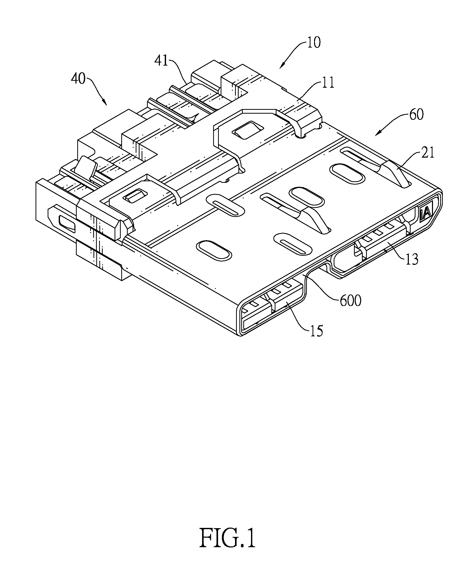
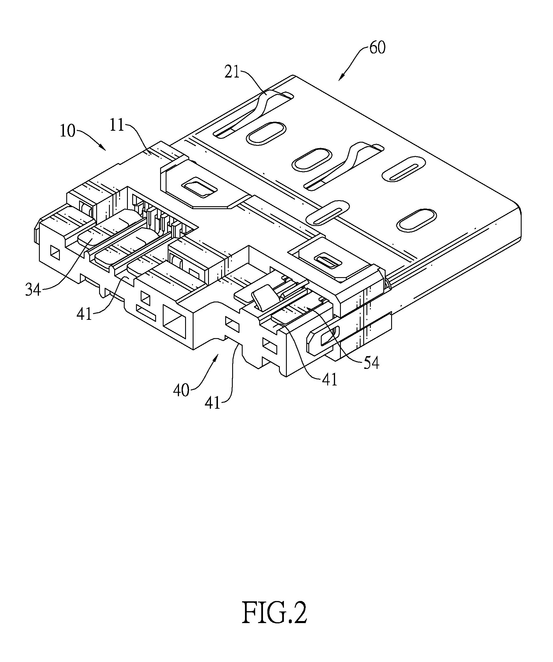
[0021]With reference to FIGS. 1 to 4, a high frequency micro connector in accordance with the present invention may be mounted on a cable and may comply with the USB 3.0 Micro-B type plug connector standard. The USB 3.0 Micro-B type standard is described in section 5.34 “USB 3.0 Micro Connector Family” of the USB 3.0 specification that is published on the USB implementers Forum (USB IF) website “http: / / www.usb.org / home”, which is incorporated herein for reference.

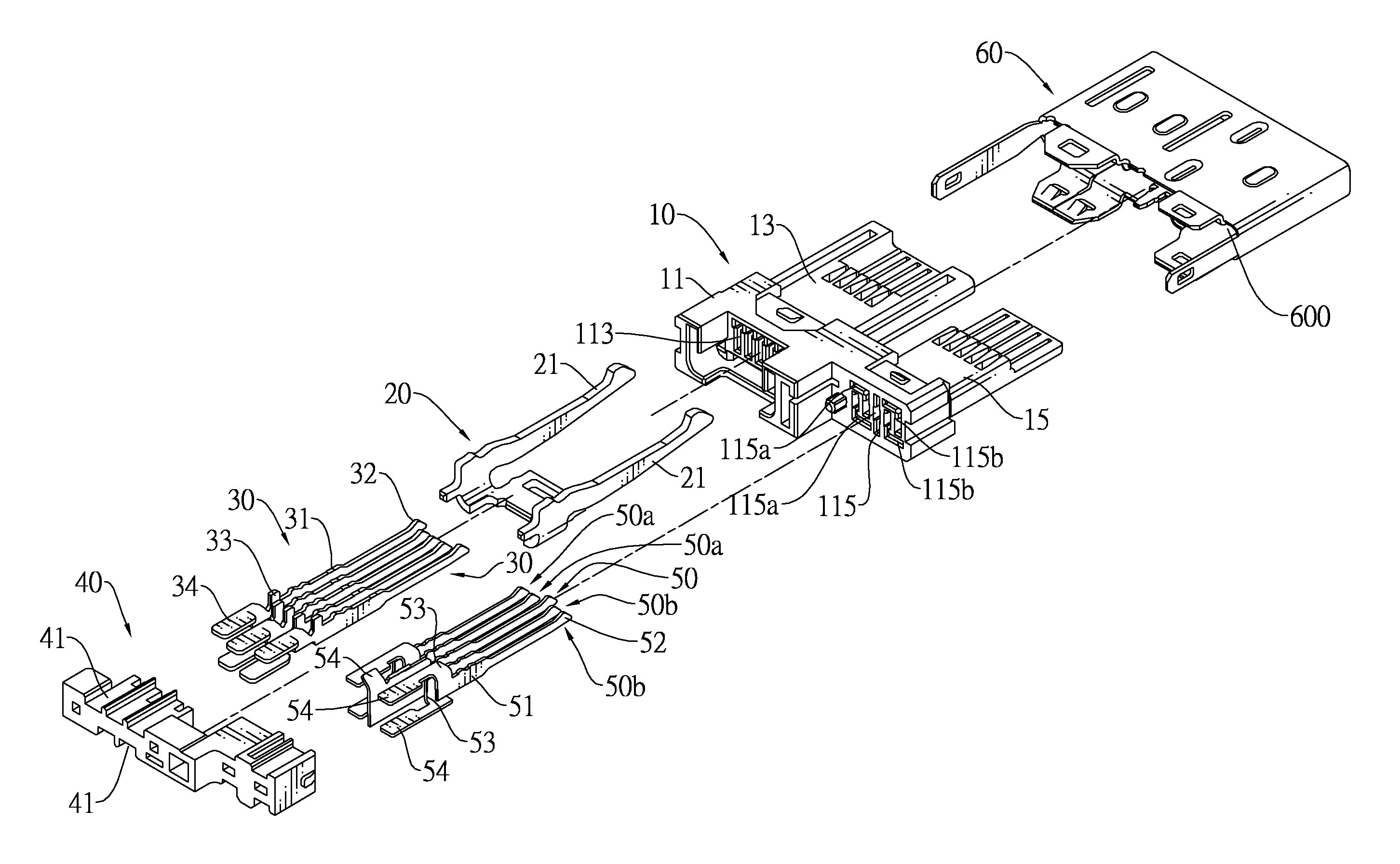
[0022]With further reference to FIGS. 5 and 6, the high frequency micro connector comprises an insulating housing (10), multiple first terminals (30), multiple second terminals (50, 50a, 50b), a fastener (20), a mounting bracket (40) and a shell (60).

[0023]The insulating housing (10) has a base (11), a first tongue (13), a second tongue (15), multiple first mounting holes (113) and multiple second mounting holes (115, 115a, 115b).

[0024]The base (11) has a front and a rear

[0025]The first tongue (13) and the second tongue (15...


PUM


Abstract

A high frequency micro connector has an insulating housing, multiple first terminals and multiple terminals. The insulating housing has a base, a first tongue and a second tongue. The first and second terminals are mounted through the base respectively on the first and second tongue. The second tongue includes pairs of high frequency signal transmission terminals each having a transverse extension section and a soldering section formed on the transverse extension section. The transverse extension sections of each pair protrude reversely and oppositely to increase the distance between the soldering sections therefore to prevent crosstalk between the high frequency signal transmission terminals.

Description

BACKGROUND OF THE INVENTION[0001]1. Field of the Invention[0002]The present invention relates to a connector, and more particularly to a high frequency micro connector that has pairs of signal transmission terminals and the signal transmission terminals of each pair are staggered to prevent crosstalk between the signal transmission terminals.[0003]2. Description of Related Art[0004]Conventional Universal Serial Bus (USB) 2.0 connectors are used popularly in various electronic devices. Most of computer peripherals are equipped with USB connectors. Because electronic devices are constantly developed to increase transmission speed thereof, the USB 2.0 protocol does not meet the current transmission speed requirement of new electronic devices. Therefore, the USB Implementers Forum sets forth new USB 3.0 protocol for higher data transmission speed.[0005]The USB 3.0 protocol is compatible with the USB 2.0 protocol and provides theoretical 5 Gbps of data transmission speed.[0006]However, a...

Claims


Application Information

Patent Timeline
Patent Type & Authority Patents(United States)
IPC IPC(8): H01R25/00H01R13/6461H01R13/658
CPCH01R13/6275H01R13/6461H01R13/6585H01R24/62
Inventor TSAI, CHENG-YUNGCHANG, MING-YUNG
Owner ADVANCED CONNECTEK INC
Why Eureka
Try Eureka