
Terminal strip

a technology of terminal strips and strips, applied in the field of terminal strips, can solve the problems of increasing gold consumption, and achieve the effect of saving gold and reducing plating costs

Inactive Publication Date: 2011-09-06
CHENG UEI PRECISION IND CO LTD
View PDF4 Cites 2 Cited by
  • Summary
  • Abstract
  • Description
  • Claims
  • Application Information

AI Technical Summary

Benefits of technology

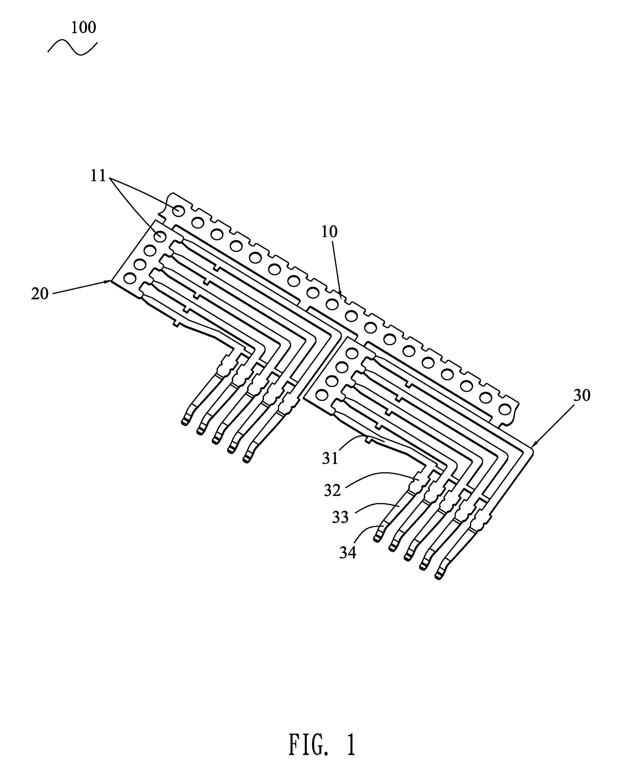
[0006]As described above, the auxiliary strip is extended from a front side of the main strip and connected with a plurality of terminals at a lateral side thereof. The elastic arm of the terminal extends beyond the auxiliary strip and is perpendicular to the main strip. As a result, when the main strip is pulled for plating the contacting portions of the terminals along a direction parallel with the main strip, it is feasible to try to avoid plating the other parts of the elastic arms, so as to save the gold and cut down the plating cost.

Problems solved by technology

As a result, the gold consumption increases.

Method used


Image

  • Terminal strip
  • Terminal strip
  • Terminal strip

Examples


Embodiment Construction

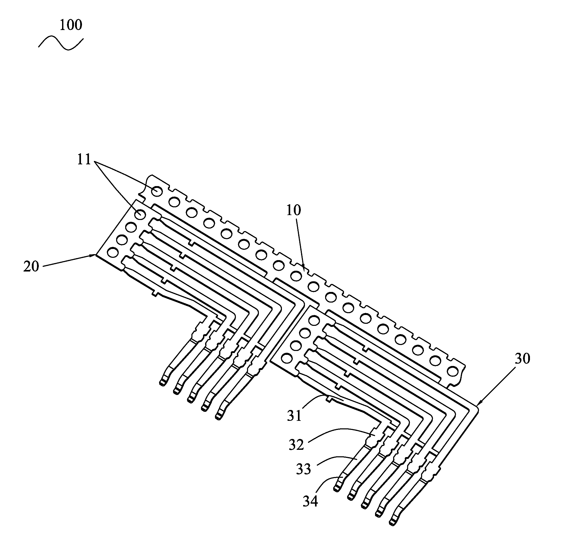
[0010]Please refer to FIG. 1, the embodiment of the invention is embodied in a terminal strip 100. The terminal strip 100 comprises a main strip 10, a plurality of spaced auxiliary strips 20 extended frontward from the main strip 10, a plurality of terminals 30 extended from the auxiliary strip 20.

[0011]The main strip 10 and the auxiliary strips 20 are punched to form holes 11 at intervals. A lateral side of the auxiliary strip 20 is extended to form a plurality of terminals 30 parallel with each other. Each of the terminals 20 has a soldering slice 31 of strip shape extending paralleled with the main strip 10. A free end of the soldering slice 31 is extended perpendicularly and opposite to the main strip 10 to form a rectangular holding portion 32. A free end of the holding portion 32 is extended frontward to form an elastic arm 33 perpendicular to the main strip 10. A free end of the elastic arm 33 is arched upwardly to form a contacting portion 34.

[0012]When the terminal strip 10...


PUM


Abstract

A terminal strip fixed to a plating machine has a main strip, a plurality of auxiliary strips extended from a side of the main strip, a plurality of terminals extended from a lateral side of the auxiliary strip. A free end of the terminal has an elastic arm extended opposite to the main strip, a free end of the elastic arm is extended beyond the auxiliary strip and forms a contacting portion. When the main strip is pulled for plating the contacting portions along a direction parallel with the main strip, it is feasible to try to avoid the other part of the elastic arm being plated, so as to save the gold and cut down the plating cost.

Description

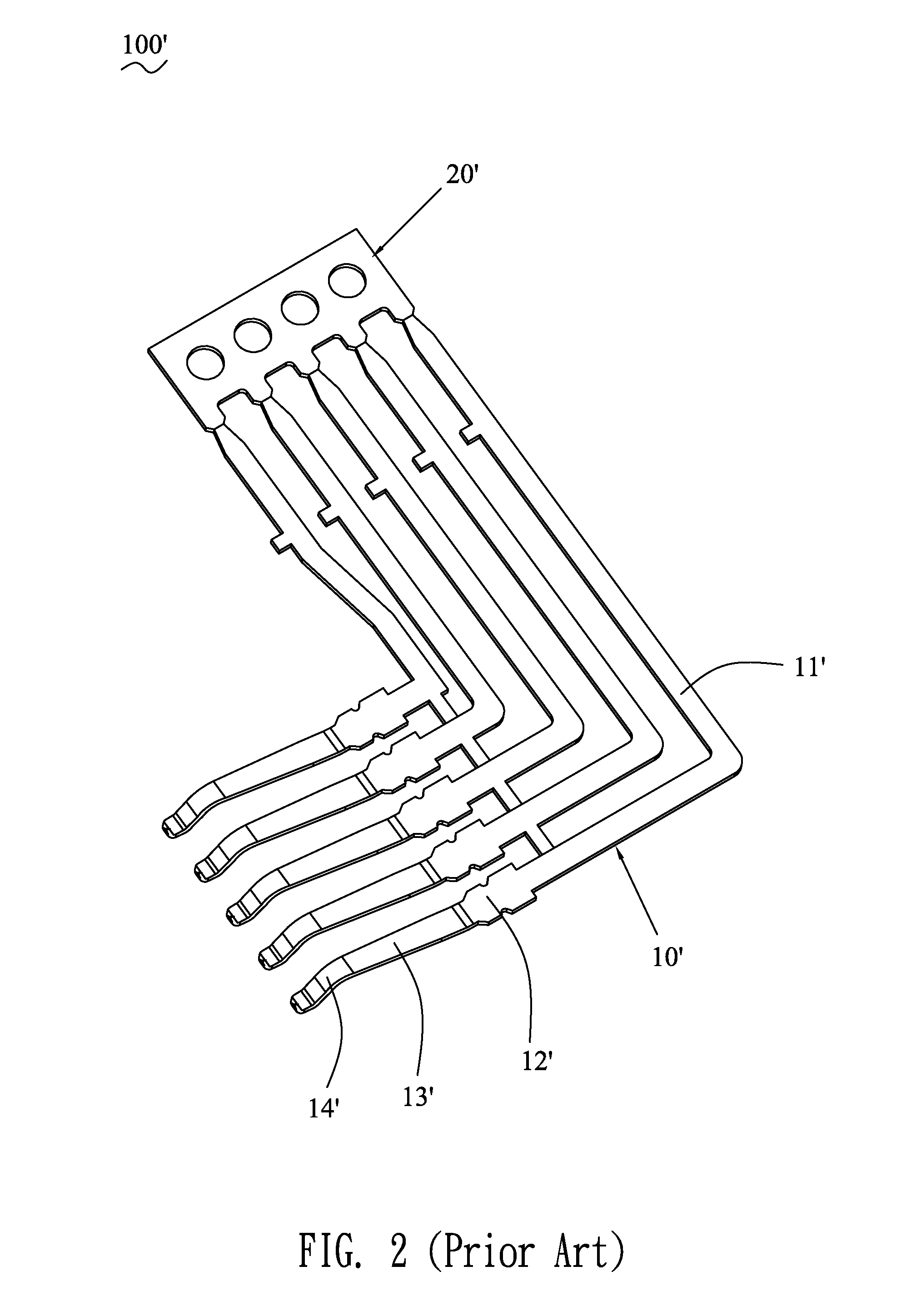
BACKGROUND OF THE INVENTION[0001]1. Field of the Invention[0002]The present invention relates to a terminal strip, and particularly to a terminal strip capable of reducing the use of gold during plating.[0003]2. The Related Art[0004]FIG. 2 shows a conventional terminal strip 100′. The terminal strip 100′ includes a connecting strip 20′ and a plurality of terminals 10′ extended from a side of the connecting strip 20′. The terminal 10′ has a soldering slice 11′ extended perpendicularly form a side of the strip 20′. A free end of the soldering slice 11′ is extended perpendicularly to form a holding portion 12′. The holding portion 12′ is extended forward to form an elastic arm 13′ substantially paralleled with the connecting strip 20′. A free end of the elastic arm 13′ is arched upwardly to form a contacting portion 14′. However, as the elastic arm 13′ is parallel with the connecting strip 20′, when the connecting strip 20′ is pulled for plating the terminals 10′, not only the contacti...

Claims


Application Information

Patent Timeline
Patent Type & Authority Patents(United States)
IPC IPC(8): H01R11/22
CPCH01R12/724H01R13/03H01R43/16H01R13/514
Inventor LAI, MING-CHUN
Owner CHENG UEI PRECISION IND CO LTD
Learn More